
Service Manual


3121231 – JLG Lift – vii
TABLE OF CONTENTS
LIST OF FIGURES
FIGURE NO. TITLE PAGE NO.
1-1. Torque Chart (SAE Fasteners - Sheet 1 of 7) . . . . . . . . . . . . . . . . . . . . . . . . . . . . . . . . . . . . . . . . .1-6
1-2. Torque Chart (SAE Fasteners - Sheet 2 of 7)) . . . . . . . . . . . . . . . . . . . . . . . . . . . . . . . . . . . . . . . .1-7
1-3. Torque Chart (SAE Fasteners - Sheet 3 of 7) . . . . . . . . . . . . . . . . . . . . . . . . . . . . . . . . . . . . . . . . .1-8
1-4. Torque Chart (SAE Fasteners - Sheet 4 of 7) . . . . . . . . . . . . . . . . . . . . . . . . . . . . . . . . . . . . . . . . .1-9
1-5. Torque Chart (METRIC Fasteners - Sheet 5 of 7)) . . . . . . . . . . . . . . . . . . . . . . . . . . . . . . . . . . . . .1-10
1-6. Torque Chart (METRIC Fasteners - Sheet 6 of 7). . . . . . . . . . . . . . . . . . . . . . . . . . . . . . . . . . . . . .1-11
1-7. Torque Chart (METRIC Fasteners - Sheet 7 of 7). . . . . . . . . . . . . . . . . . . . . . . . . . . . . . . . . . . . . .1-12
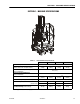
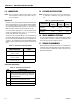
3-1. Base Components. . . . . . . . . . . . . . . . . . . . . . . . . . . . . . . . . . . . . . . . . . . . . . . . . . . . . . . . . . . . . .3-1
3-2. Wheel Lug Nut Tightening Sequence . . . . . . . . . . . . . . . . . . . . . . . . . . . . . . . . . . . . . . . . . . . . . . .3-3
4-1. Control Components Location - MVL/MSP. . . . . . . . . . . . . . . . . . . . . . . . . . . . . . . . . . . . . . . . . . .4-1
4-2. Component Electrical Connections. (2-12V Batteries shown) . . . . . . . . . . . . . . . . . . . . . . . . . . . .4-6
4-3. Battery Cable to Battery Terminal Connections (4-6V). . . . . . . . . . . . . . . . . . . . . . . . . . . . . . . . . .4-7
4-4. Ground Control Module Components. . . . . . . . . . . . . . . . . . . . . . . . . . . . . . . . . . . . . . . . . . . . . . .4-8
4-5. Platform Control Console Components.. . . . . . . . . . . . . . . . . . . . . . . . . . . . . . . . . . . . . . . . . . . . .4-16
4-6. Hydraulic Pressure Adjustment Screw. (Machine Rear Covers Removed) . . . . . . . . . . . . . . . . . .4-20
4-7. Typical Hydraulic Pressure Gauge Installation (Hydraulic Filter Removed). . . . . . . . . . . . . . . . . .4-20
4-8. Typical Hydraulic Pressure Gauge Installation (After Hydraulic Filter). . . . . . . . . . . . . . . . . . . . . .4-21
4-9. Obstruction Sensor System Components (Platform Cutaway) . . . . . . . . . . . . . . . . . . . . . . . . . . .4-29
5-1. Mast Components. (MVL/MSP). . . . . . . . . . . . . . . . . . . . . . . . . . . . . . . . . . . . . . . . . . . . . . . . . . . .5-1
5-2. MVL/MSP - Mast Chain and Sequence Cable Adjustment Components. . . . . . . . . . . . . . . . . . . .5-3
5-3. Machine Positioned for Cylinder Removal.. . . . . . . . . . . . . . . . . . . . . . . . . . . . . . . . . . . . . . . . . . .5-9
5-4. Lift Cylinder Component Cross-Section (MVL/MSP). . . . . . . . . . . . . . . . . . . . . . . . . . . . . . . . . . . .5-13
5-5. Mast Section - Assembly Reference. . . . . . . . . . . . . . . . . . . . . . . . . . . . . . . . . . . . . . . . . . . . . . . .5-16
5-6. Mast Chain Routing Diagram. - MVL/MSP . . . . . . . . . . . . . . . . . . . . . . . . . . . . . . . . . . . . . . . . . . .5-18
5-7. Mast Bottom End - Slide Pad Installation . . . . . . . . . . . . . . . . . . . . . . . . . . . . . . . . . . . . . . . . . . . .5-19
5-8. MSP - StockPicker Platform Installation.. . . . . . . . . . . . . . . . . . . . . . . . . . . . . . . . . . . . . . . . . . . . .5-27
6-1. Voltage Measurement (DC). . . . . . . . . . . . . . . . . . . . . . . . . . . . . . . . . . . . . . . . . . . . . . . . . . . . . . .6-3
6-2. Resistance Measurement . . . . . . . . . . . . . . . . . . . . . . . . . . . . . . . . . . . . . . . . . . . . . . . . . . . . . . . .6-3
6-3. Continuity Measurement . . . . . . . . . . . . . . . . . . . . . . . . . . . . . . . . . . . . . . . . . . . . . . . . . . . . . . . . .6-4
6-4. Current Measurement (DC). . . . . . . . . . . . . . . . . . . . . . . . . . . . . . . . . . . . . . . . . . . . . . . . . . . . . . .6-4
6-5. Component Electrical Connections. . . . . . . . . . . . . . . . . . . . . . . . . . . . . . . . . . . . . . . . . . . . . . . . .6-9
6-6. Overview of Electrical System Components. (MVL/MSP) (Sheet 1 of 2) . . . . . . . . . . . . . . . . . . . .6-48
6-7. Electrical Diagram. (MVL/MSP) (Sheet 1) . . . . . . . . . . . . . . . . . . . . . . . . . . . . . . . . . . . . . . . . . . . .6-50
6-8. Hydraulic Diagram. (MVL/MSP) . . . . . . . . . . . . . . . . . . . . . . . . . . . . . . . . . . . . . . . . . . . . . . . . . . .6-52