Operation and Safety Manual Original Instructions - Keep this manual with the machine at all times.
NOTES:
SECTION - FOREWORD FOREWORD This manual is a very important tool! Keep it with the machine at all times. The purpose of this manual is to provide owners, users, operators, lessors, and lessees with the precautions and operating procedures essential for the safe and proper machine operation for its intended purpose. Due to continuous product improvements, JLG Industries, Inc. reserves the right to make specification changes without prior notification. Contact JLG Industries, Inc. for updated information.
SECTION - SAFETY ALERT SYMBOLS AND SAFETY SIGNAL WORDS SAFETY ALERT SYMBOLS AND SAFETY SIGNAL WORDS This is the Safety Alert Symbol. It is used to alert you to the potential personal injury hazards. Obey all safety messages that follow this symbol to avoid possible injury or death INDICATES AN IMMINENTLY HAZARDOUS SITUATION. IF NOT AVOIDED, WILL RESULT IN SERIOUS INJURY OR DEATH. THIS DECAL WILL HAVE A RED BACKGROUND. INDICATES A POTENTIALITY HAZARDOUS SITUATION.
SECTION - SAFETY ALERT SYMBOLS AND SAFETY SIGNAL WORDS For : THIS PRODUCT MUST COMPLY WITH ALL SAFETY RELATED BULLETINS. CONTACT JLG INDUSTRIES, INC. OR THE LOCAL AUTHORIZED JLG REPRESENTATIVE FOR INFORMATION REGARDING SAFETY RELATED BULLETINS WHICH MAY HAVE BEEN ISSUED FOR THIS PRODUCT. • Accident Reporting • Product Safety Publications • Current Owner Updates • Questions Regarding Product Safety JLG INDUSTRIES, INC. SENDS SAFETY RELATED BULLETINS TO THE OWNER OF RECORD OF THIS MACHINE.
SECTION - REVISION LOG REVISION LOG Original Issue of Manual . . . . . . . . . . . . . . November 29, 2005 Manual Revised. . . . . . . . . . . . . . . . . . . . . . . . . . April 19, 2006 Manual Revised. . . . . . . . . . . . . . . . . . . . . . . . October 4, 2006 Manual Revised. . . . . . . . . . . . . . . . . . . . . . . . . . . April 2, 2007 Manual Revised. . . . . . . . . . . . . . . . . . . . . . November 6, 2007 Manual Revised. . . . . . . . . . . . . . . . . . . . . . . . . .
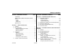
TABLE OF CONTENTS SECTION - PARAGRAPH, SUBJECT PAGE FOREWORD . . . . . . . . . . . . . . . . . . . . . . . . . . . . . . . . . . SAFETY ALERT SYMBOLS AND SAFETY SIGNAL WORDS. . . . . . . . . . . . . . . . . . . . . . . . . . . . . . . . . . . . . . Contact : . . . . . . . . . . . . . . . . . . . . . . . . . . . . . . . . . . . In USA:. . . . . . . . . . . . . . . . . . . . . . . . . . . . . . . . . . . . . Outside USA: . . . . . . . . . . . . . . . . . . . . . . . . . . . . . . . . REVISION LOG . . . . .
TABLE OF CONTENTS SECTION - PARAGRAPH, SUBJECT PAGE Brake Release Button . . . . . . . . . . . . . . . . . . . . . . . . 3-7 Platform Up . . . . . . . . . . . . . . . . . . . . . . . . . . . . . . . . 3-9 Platform Down . . . . . . . . . . . . . . . . . . . . . . . . . . . . . 3-9 Manual Descent Control Valve . . . . . . . . . . . . . . . . . 3-9 Machine Status LCD Display . . . . . . . . . . . . . . . . . 3-10 LCD Display Fault Conditions. . . . . . . . . . . . . . . . . 3-11 3.
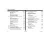
TABLE OF CONTENTS SECTION - PARAGRAPH, SUBJECT PAGE SECTION - PARAGRAPH, SUBJECT Hanging a Rug using the Rug Carrier Accessory Arms . . . . . . . . . . . . . . . . . . . . . . . . . . . 3-41 Removing a Rug using Rug Carrier Accessory Arms. . . . . . . . . . . . . . . . . . . . . . . . . . . . 3-43 3.15 STOCK-PICKER HANGER ACCESSORY. . . . . . . . . . 3-45 Pre-Start Inspection . . . . . . . . . . . . . . . . . . . . . . . . . 3-45 Loading and Transporting an Item using the Hanger Accessory . . . . . . . .
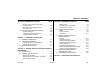
TABLE OF CONTENTS SECTION - PARAGRAPH, SUBJECT PAGE SECTION - PARAGRAPH, SUBJECT LIST OF FIGURES 2-1. LIST OF TABLES Daily Walk-Around Inspection for MVL/MSP Machines. . . . . . . . . . . . . . . . . . . . . . . . 2-6 2-2. Pot-Hole-Protection Bars Lowered. . . . . . . . . . . . . 2-7 3-1. Ground Control Station. (Machine Rear View). . . . 3-8 3-2. Platform Control Console . . . . . . . . . . . . . . . . . . . 3-15 3-3. Platform Control Display Panel. . . . . . . . . . . . . . . 3-17 3-4.
SECTION 1 - SAFETY PRECAUTIONS SECTION 1. SAFETY PRECAUTIONS 1.1 GENERAL 1.2 This section outlines the necessary precautions for proper and safe machine usage and maintenance. For proper machine use, it is mandatory that a daily routine is established based on the content of this manual.
SECTION 1 - SAFETY PRECAUTIONS • All operating personnel must be familiar with the emergency controls and emergency operation of the machine as specified in this manual. • Read, understand, and obey all applicable employer, local, and governmental regulations as they pertain to operation of the machine. Workplace Inspection • The operator is to take safety measures to avoid all hazards in the work area prior to machine operation.
SECTION 1 - SAFETY PRECAUTIONS 1.3 OPERATION • When performing welding operations at elevation, precautions must be taken to protect all machine components from contact with weld splatter or molten metal. General • Battery fluid is highly corrosive. Avoid contact with skin and clothing at all times. • Do not use the machine for any purpose other than positioning personnel, their tools and equipment, or for hand stock picking. • Never operate a machine that is not working properly.
SECTION 1 - SAFETY PRECAUTIONS • Before operating the machine, make sure all railing and gates are fastened in their proper position. Electrocution Hazards • This machine is not insulated and does not provide protection from contact or proximity to electrical current. • Keep both feet firmly positioned on the platform floor at all times. Never use ladders, boxes, steps, planks, or similar items on platform to provide additional reach. • Never use the mast assembly to enter or leave the platform.
SECTION 1 - SAFETY PRECAUTIONS Table 1-1. Minimum Approach Distances (M.A.D.
SECTION 1 - SAFETY PRECAUTIONS Tipping Hazard • Do not elevate platform or drive with platform elevated while on a slope, or on an uneven or soft surface. • The user should be familiar with the surface before driving. Do not exceed the allowable sideslope and grade while driving. • Before driving on floors, bridges, trucks, and other surfaces, check allowable capacity of the surfaces. • Never exceed the maximum platform capacity. Distribute loads evenly on platform floor.
SECTION 1 - SAFETY PRECAUTIONS Crushing And Collision Hazard • Keep non-operating personnel at least 6 ft. (1.8m) away from machine during all driving operations. • Personal protection equipment must be worn by all operating and ground personnel. • Check work area clearances above, on sides, and bottom of platform while driving and lifting or lowering platform.
SECTION 1 - SAFETY PRECAUTIONS 1.4 Towing, Lifting, And Hauling • Do not assist a stuck or disabled machine by pushing or pulling except by pulling at the chassis tie-down bars. • Never allow personnel in platform while towing, lifting, or hauling. • This machine should not be towed, except in the event of emergency, malfunction, power failure, or loading/unloading. Refer to the Emergency Procedures Section of this manual for emergency towing procedures.
SECTION 2 - PREPARATION AND INSPECTION SECTION 2. PREPARATION AND INSPECTION 2.1 PERSONNEL TRAINING Operator Training The aerial platform is a personnel handling device; so it is necessary that it be operated and maintained only by trained personnel. Operator training must cover: Persons under the influence of drugs or alcohol or who are subject to seizures, dizziness or loss of physical control must not operate this machine. 1.
SECTION 2 - PREPARATION AND INSPECTION 2.2 Training Supervision Training must be done under the supervision of a qualified person in an open area free of obstructions until the trainee has developed the ability to safely control and operate the machine. Operator Responsibility The operator must be instructed that he/she has the responsibility and authority to shut down the machine in case of a malfunction or other unsafe condition of either the machine or the job site.
SECTION 2 - PREPARATION AND INSPECTION Table 2-1. Inspection and Maintenance Table TYPE PRIMARY RESPONSIBILITY FREQUENCY SERVICE QUALIFICATION REFERENCE Pre-Start Inspection Before using each day; or whenever there’s an Operator change. User or Operator User or Operator Operator and Safety Manual Pre-Delivery Inspection (See Note) Before each sale, lease, or rental delivery.
SECTION 2 - PREPARATION AND INSPECTION 2.3 PRE-START INSPECTION 6. Hydraulic Oil – Check the hydraulic oil level. NOTE: The Pre-Start Inspection should include each of the following: 1. Cleanliness – Check all surfaces for leakage (oil, fuel, or battery fluid) or foreign objects. Report any leakage to the proper maintenance personnel. FILL TO LINE on Hydraulic Reservoir indicates the proper level for hydraulic oil. 2. Decals and Placards – Check all for cleanliness and legibility.
SECTION 2 - PREPARATION AND INSPECTION 2.4 DAILY WALK-AROUND INSPECTION Begin the “Walk-Around Inspection” at item one (1) as noted on the diagram. Continue around machine check each item in sequence for the conditions listed in the following check list. TO AVOID POSSIBLE INJURY, BE SURE MACHINE POWER IS “OFF” DURING “WALK-AROUND INSPECTION”. 2. Base Frame - Check pot-hole-protection system components; check for loose wires or cables dangling below the base. 3.
SECTION 2 - PREPARATION AND INSPECTION 1. 2. 3. 4. 5. 6. 7. 8. 9. Drive and Caster Wheels Base Frame Manual Descent Control Valve Motor/Pump/Reservoir Unit Batteries - (Inside Cover) Platform Assembly Platform Control Console Ground Control Station Mast Assembly Figure 2-1. Daily Walk-Around Inspection for MVL/MSP Machines.
SECTION 2 - PREPARATION AND INSPECTION 2.5 Function Check Once the “Walk-Around” Inspection is complete, perform a function check of all systems in an area free of overhead and ground level obstructions. Refer to Section 3 for more specific operating instructions. IF THE MACHINE DOES NOT OPERATE PROPERLY, TURN OFF THE MACHINE IMMEDIATELY! REPORT THE PROBLEM TO THE PROPER MAINTENANCE PERSONNEL. DO NOT OPERATE THE MACHINE UNTIL IT IS DECLARED SAFE FOR OPERATION. Perform a Function Check as follows: 1.
SECTION 2 - PREPARATION AND INSPECTION machine will indicate a tilt condition if any attempt is made to elevate the platform. • Drive Speed Reduction Limit - When platform is elevated more than 1.5 to 2 ft. (.5m) drive speed is cut to 1/4 of platform lowered drive speed. 2-8 – JLG Lift – • Platform Joystick Enable Trigger - The machine will not operate (drive or lift) unless this switch is pressed and held during drive or lift operation. d.
SECTION 3 - MACHINE CONTROLS, INDICATORS AND OPERATION SECTION 3. MACHINE CONTROLS, INDICATORS AND OPERATION 3.1 GENERAL 3.2 MACHINE DESCRIPTION THE MANUFACTURER HAS NO DIRECT CONTROL OVER MACHINE APPLICATION AND OPERATION. THE USER AND OPERATOR ARE RESPONSIBLE FOR CONFORMING WITH GOOD SAFETY PRACTICES. This section provides the necessary information needed to understand control function and operation.
SECTION 3 - MACHINE CONTROLS, INDICATORS AND OPERATION 3.3 MACHINE OPERATION 3.4 BATTERY CHARGING Getting Started This machine is equipped with an AC voltage input/DC voltage output battery charger. The charger automatically terminates charging when the batteries reach full capacity. The following control conditions must be met before the machine can be operated from either the Ground or Platform Controls. • The batteries contain enough voltage to operate the machine.
SECTION 3 - MACHINE CONTROLS, INDICATORS AND OPERATION Battery - Low Voltage Warning Indicators The MVL/MSP Platform Control Console and Ground Control Station indicate battery low voltage at three (3) Warning Levels. Table 3-1. Battery Low Voltage Warning Indicators. WARNING LEVEL INDICATOR LOCATION PLATFORM CONTROL LED RESULT GROUND CONTROL LCD ACTION REQUIRED TO CLEAR FAULT LEVEL-1 • 3 LEDs/BARS Flashing with an Charge batteries to a level of four (4) audible beep.
SECTION 3 - MACHINE CONTROLS, INDICATORS AND OPERATION To Charge Batteries 1. Park machine in a well ventilated area near an AC voltage electrical outlet. 2. Always use a grounded AC outlet. Connect charger to an outlet that has been properly installed and grounded in accordance with all local codes and ordinances. A grounded outlet is required to reduce risk of electric shock – do not use ground adapters or modify plug.
SECTION 3 - MACHINE CONTROLS, INDICATORS AND OPERATION power will also be reduced to maintain a maximum internal temperature. 3. When the GREEN ‘CHARGED’ LED turns on, the batteries are completely charged. 4. If a fault occurred anytime during charging, a fault indication is given by flashing the RED ‘FAULT’ LED with a code corresponding to the error.
SECTION 3 - MACHINE CONTROLS, INDICATORS AND OPERATION [3 FLASH] Charge Timeout: Indicates the battery did not charge within the allowed time. This could occur if the battery is of a larger capacity than the algorithm is intended for. It can also occur if the battery pack is damaged, old, or in poor condition. In unusual cases it could mean charger output is reduced due to high ambient temperature.
SECTION 3 - MACHINE CONTROLS, INDICATORS AND OPERATION 3.5 GROUND CONTROL STATION - OPERATION POWER ON (See Figure 3-1.) TURN CLOCKWISE and RELEASE - NOTE: If equipped with optional Programmable Security Lock (PSL) see Section 3.12 for additional instructions. To Reset Emergency Stop Main Power Selector Switch Set the Main Power Selector Switch to Ground Control Mode for Ground Control operation or Platform Control Mode for Platform Operation.
SECTION 3 - MACHINE CONTROLS, INDICATORS AND OPERATION Ground Control Module 1. 2. 3. 4. 5. 6. Machine Status LCD Display Main Power Selector Switch Emergency Stop Brake Release Platform Up Platform Down Battery Charging Station 7. Battery Charging Status Indicators 8. Charger A/C Input Receptacle Hydraulic System 9. Hydraulic Oil Reservoir 10. Manual Descent Control Valve NOTE: The Ground Control Station Module is fully programmable. For operator level programmability see Section 5.
SECTION 3 - MACHINE CONTROLS, INDICATORS AND OPERATION Platform Up Manual Descent Control Valve PUSH IN TO ELEVATE Platform PUSH-IN TO LOWER Platform RELEASE TO STOP ELEVATING Platform Down PUSH IN TO LOWER Platform RELEASE TO STOP Platform Descent RELEASE TO STOP LOWERING 3121230 – JLG Lift – 3-9
SECTION 3 - MACHINE CONTROLS, INDICATORS AND OPERATION Machine Status LCD Display 1 2 00 00000.0 3 4 At power-up and during operation the LCD display on the Ground Control Module displays the current machine operating status. The following illustration explains the symbol indications. 00 5 LCD Display Symbols 1. 2. 3. 4. 5.
SECTION 3 - MACHINE CONTROLS, INDICATORS AND OPERATION In the LCD Display Symbols illustration item (2), the Function Display or Function Disabled Indicators will vary as shown following: DRIVE Disabled LCD Display Fault Conditions Table 3-2, LCD Display - Operation Fault Conditions show common LCD display Fault indications which may occur during operation and are usually caused by either an error in machine operation or a work area condition.
SECTION 3 - MACHINE CONTROLS, INDICATORS AND OPERATION Table 3-2.
SECTION 3 - MACHINE CONTROLS, INDICATORS AND OPERATION Table 3-2. LCD Display - Operation Fault Conditions (Continued) FAULT CODE PLATFORM LEDS FLASHING 4 3 LCD SYMBOL SCREEN 00000.0 FAULT DESCRIPTION/ MACHINE CONDITION LCD TEXT SCREEN 04 04 LOOK FOR THIS Tilt Condition (Platform Elevated) DRIVE and Lift UP Disabled Lower the Platform and Drive off the Tilt Condition Drive Motor Brushes Require Service Replacement (See Section 5.
SECTION 3 - MACHINE CONTROLS, INDICATORS AND OPERATION Table 3-2. LCD Display - Operation Fault Conditions (Continued) FAULT CODE PLATFORM LEDS FLASHING 34 — Aux. #1 - Platform Gate Open or Close Platform Gate or Depress No Pressure on the Platform Platform Enable switch during Enable switch. machine operation. 35 — Aux. #1 - Platform Enable switch depressed during Machine Power-up.
SECTION 3 - MACHINE CONTROLS, INDICATORS AND OPERATION 3.6 PLATFORM CONTROL CONSOLE OPERATION 8 1. On/Off Key Switch (See page 3-16) 2. Emergency Stop/Shut Down Button (See page 3-17) 3. Function Enable Lever - (on front of joystick) (See page 3-19) 4. Multifunction Joystick Control (See page 3-20) 5. Drive Speed Setting Selector Switch (See page 3-23) 6. Platform Control Display Panel (See page 3-17) 7. Horn Button - (See page 3-19) 8.
SECTION 3 - MACHINE CONTROLS, INDICATORS AND OPERATION General Platform On/Off Key Switch The following conditions must be met before the machine can be operated from the platform control console: 1 • Ground Control Station - Main Power Selector Switch must be set to PLATFORM CONTROL MODE. 2 • Ground Control Station - Emergency Stop/Shut Down Button must be in the RESET position (POWER ON). NOTE: At the Platform Control Console Set the On/Off Key Switch to the ON position (2) to operate machine. 1.
SECTION 3 - MACHINE CONTROLS, INDICATORS AND OPERATION Platform Emergency Stop Button NOTE: Platform Control Display Panel The Platform and Ground Control Station Emergency Stop Buttons must both be in the RESET position to operate machine. 1 4 3 POWER OFF 2 PUSH IN TO ENGAGE Emergency Stop POWER ON TURN CLOCKWISE and RELEASE to RESET Emergency Stop Figure 3-3. Platform Control Display Panel. 1. Battery Charge/Flash Code LEDS 2. Drive Mode Indicator 3121230 – JLG Lift – 3. Lift Mode Indicator 4.
SECTION 3 - MACHINE CONTROLS, INDICATORS AND OPERATION NOTE: 1. Battery Charge/Flash Code Indicator LEDS On normal power-up and operation this series of ten (10) LEDs visually indicates the amount of charge remaining in the batteries. The number of LEDs lit will change depending on the level of charge in the batteries. • (+) All Three (3) GREEN LEDs lit up indicate maximum battery charge. • Four (4) YELLOW LEDs indicate a two thirds to one third battery charge remaining.
SECTION 3 - MACHINE CONTROLS, INDICATORS AND OPERATION Drive/Lift Mode Selector Switch 1 2 Horn Button When the machine is powered on, pressing this button will sound the Horn. Drive/Lift Mode Selector Switch 1. LIFT Mode 2. DRIVE Mode PUSH the rocker switch to select mode of operation. Whichever mode is selected the appropriate LED indicator on the display panel below will light up showing which mode has been activated for joystick operation.
SECTION 3 - MACHINE CONTROLS, INDICATORS AND OPERATION Multifunction Joystick Control Drive Mode The joystick will operate the following machine functions: 1. Activate the Drive Mode using the Drive/Lift Mode Selector switch. • Drive/Steer • Platform Lift Up and Down NOTE: Use the Drive/Lift Mode Selector Switch to select which function the joystick will operate. The selected operating mode will only remain active for 5 seconds if the function is not operated.
SECTION 3 - MACHINE CONTROLS, INDICATORS AND OPERATION GRAD E SMOOTH, FIRM AND LEVEL SIDESLOPE DO NOT DRIVE MACHINE ON A GRADE OR SIDESLOPE EXCEEDING THOSE SPECIFIED IN SECTION 5 - MACHINE SPECIFICATIONS Figure 3-4.
SECTION 3 - MACHINE CONTROLS, INDICATORS AND OPERATION Lift Mode 1. Activate the Lift Mode using the Drive/Lift Mode Selector switch. IF THE TILT ALARM WARNING HAS BEEN ACTIVATED WHILE DRIVING WITH THE PLATFORM ELEVATED, LOWER PLATFORM COMPLETELY AND DRIVE TO A FIRM LEVEL SURFACE. ENSURE THE AREA BENEATH THE PLATFORM IS FREE OF PERSONNEL PRIOR TO LOWERING THE PLATFORM. 2 3 3-22 2. Platform LIFT DOWN Direction 3.
SECTION 3 - MACHINE CONTROLS, INDICATORS AND OPERATION Drive Speed Setting Controls NOTE: Drive Speed Setting Selector Switch When the platform is elevated the maximum drive speed is automatically cut-back to 1/4th the speed when the platform is fully lowered. The Ground Control ModuleLCD screen will display a turtle when in this mode, See page 3-11 - Ground Control - LCD Status Display in this section of the manual. 1.
SECTION 3 - MACHINE CONTROLS, INDICATORS AND OPERATION 3.7 PARKING MACHINE 3.8 PLATFORM CONFIGURATIONS 1. Drive machine to a well-protected and well-ventilated area. 2. Ensure the platform is fully lowered, turn the main power selector switch to the OFF position (centered). NOTE: 3-24 If required, charge batteries in preparation for next work day.
SECTION 3 - MACHINE CONTROLS, INDICATORS AND OPERATION 2 1 3 FRONT GULL-WING ENTRY PLATFORM (NON-CE and AUS) Model Max. Capacity Model Max. Capacity 15MVL 500 lb. (230kg) 15MVL 500 lb. (230kg) 20MVL 350 lb. (160kg) 20MVL 1. Front Gull-Wing Entry Gate 2. Entry Gate Latch 3121230 FRONT SLIDE BAR ENTRY PLATFORM 3. Lanyard Attach Point (Left side on mast) 1. Sliding Side Entry Gate 2. Platform Control Console – JLG Lift – 350 lb. (160kg) 3.
SECTION 3 - MACHINE CONTROLS, INDICATORS AND OPERATION Table 3-3. Max. Capacity with Side Entry Platform w/Folding Material Tray Installed 2 3 SPEC 4 ANSI/ CSA CE Model(1) Platform Capacity Tray Capacity Combined Capacity 15MSP 300 lb. (136 kg) 150 lb. (70 kg) 450 lb. (206 kg) 20MSP 300 lb. (136 kg) 150 lb (70 kg) 450 lb. (206 kg) 20MVL 250 lb. (115 kg) 100 lb. (45 kg) 350 lb. (160 kg) 15MVL 350 lb. (160 kg) 150 lb. (70 kg) 500 lb. (230 kg) 20MVL 250 lb. (115 kg) 100 lb.
SECTION 3 - MACHINE CONTROLS, INDICATORS AND OPERATION EXTENDIBLE PLATFORM (GULL-WING ENTRY - NON CE and AUS) Max. Capacity Model Max. Capacity 15MVL/15MSP 500 lb. (230 kg) 15MVL/15MSP 500 lb. (230 kg) 20MVL/20MSP 350 lb. (160kg) 20MVL/20MSP 1. Gullwing Entry Gate 2. Entry Gate Latch 3. Lanyard Attach Point (on mast) 3121230 EXTENDIBLE PLATFORM (FRONT SLIDE BAR ENTRY - CE ONLY) Model 4. Extension Slide/Lock Handle 5. Platform Control Console 6. Sliding Extendible Section – JLG Lift – 1.
SECTION 3 - MACHINE CONTROLS, INDICATORS AND OPERATION StockPicking Platform Operation The stockpicking platform is available in two (2) versions. • Fixed side-rail version • Folding side-rail version THE STOCKPICKER PLATFORM ALLOWS THE MACHINE TO BE OPERATED IN AN OPEN RAIL CONFIGURATION (SEE ILLUSTRATION). CE SPECIFICATION MACHINES: THE OPERATOR MUST WEAR A FULL BODY HARNESS EQUIPPED WITH A LANYARD SHORT ENOUGH TO PREVENT A FALL FROM THE PLATFORM.
SECTION 3 - MACHINE CONTROLS, INDICATORS AND OPERATION STOCKPICKER PLATFORM (OPEN RAIL CONFIGURATION) (MSP) 1. Platform Mid-Gate (enter platform behind mid-gate and close the mid-gate when driving with front rails open). 2. Open Rail Configuration work area. (See Caution on previous page about fall protection requirements). 3. Platform Control Console attached to fixed side-rail in the rear of the platform.
SECTION 3 - MACHINE CONTROLS, INDICATORS AND OPERATION 3.9 FALL PROTECTION - LANYARD ATTACHMENT JLG INDUSTRIES, INC. RECOMMENDS THE OPERATOR IN THE PLATFORM WEAR A FULL BODY HARNESS WITH A LANYARD ATTACHED TO AN AUTHORIZED LANYARD ANCHORAGE POINT. The lanyard attach point for MVL/MSP machines depends on the type of platform attached to the machine. • Quick Change (removable) platforms use a lanyard attach point located on the lower left side of the mast header, just behind the platform (see illustration).
SECTION 3 - MACHINE CONTROLS, INDICATORS AND OPERATION 3.10 QUICK-CHANGE PLATFORM MOUNTING MVL Model Lifts are equipped with quick-change platform mounts which allow quick removal and installation of currently available quick-change platforms. NOTE: MSP Models require the installation of the Quick-Change mount kit to use Quick-Change Platforms. 1 Platform Removal (see illustration following) 1. Remove the platform control console from the platform and lay aside. 2 2.
SECTION 3 - MACHINE CONTROLS, INDICATORS AND OPERATION 3.11 TRANSPORTING, LIFTING AND TIE DOWN PROCEDURES the mast (rear) end of the machine, using the rear tie-down loop attached to the base frame. General All MVL and MSP Model Personnel Lifts may be transported to a work site using the following methods: • Driving the machine around on its base wheels if travel surface area permits.
SECTION 3 - MACHINE CONTROLS, INDICATORS AND OPERATION Machine Tie-Down Crane Hook Accessory (Option) With machine in position to be tied down and brakes engaged, use the following guidelines for restraining the machine during transport. The crane hook accessory provides an attachment point for a lifting device to lift the machine. The lifting device must be capable of handling the gross weight of the machine, see the machine specifications Section 5 of this manual.
SECTION 3 - MACHINE CONTROLS, INDICATORS AND OPERATION Fork-Lift Truck Transport All MVL and MSP Model Lifts are equipped with wide fork-lift pockets running the length of the base frame and also through the sides of the base. (See Figure 3-6.) This allows the machine to be either transported around a work area or lifted onto a higher level using a standard fork-lift truck.
SECTION 3 - MACHINE CONTROLS, INDICATORS AND OPERATION Figure 3-6. Forklift Truck Lifting Pockets and Machine Tie Down Loop Locations. 1. Rear Tie-Down Loop 2. Side Fork Lift Pockets 3. No Rear Fork Lifting Decal 3121230 4. Front Tie-Down Loop 5.
SECTION 3 - MACHINE CONTROLS, INDICATORS AND OPERATION 3.12 PROGAMMABLE SECURITY LOCK (PSL™) (MVL/MSP - OPTION) 1 2 3 PSL™ The optional Programmable Security Lock switch can be programmed with a four (4) digit operators code to allow only those persons with the code to power-up and operate the machine. PSL™ Box and Ground Control Locations 6 1 2 3 4 5 6 7 8 9 4 5 0 Figure 3-7. PSL™ Switch & Ground Control Station Locations - At Rear of Machine. Figure 3-8.
SECTION 3 - MACHINE CONTROLS, INDICATORS AND OPERATION Machine Power Up using the PSL™ Changing the Operator’s Code NOTE: When entering code on the key pad, a short beep indicates a properly depressed key, a long beep indicates an error in depressing key. If an error occurs, you must restart the code entry process again. The PSL Operators Code can be changed by a supervisor should the need occur.
SECTION 3 - MACHINE CONTROLS, INDICATORS AND OPERATION 3.13 OBSTRUCTION SENSING SYSTEM (MSP OPTION) Operation NOTE: System Description The Obstruction Sensing System (OSS) is designed to detect the presence of obstructions within a predetermined detection zone beneath the platform, when lowering the platform from an elevated position. NOTE: The OSS only operates normally when the Ground Control Module - Power Selector Switch is set to PLATFORM CONTROL MODE.
SECTION 3 - MACHINE CONTROLS, INDICATORS AND OPERATION OSS Pre-Start Inspection 1 (See Figure 3-10.) From ground controls, raise platform approximately 5'-6'. The RED LED on the electronic module will be illuminated when power is applied. If an obstruction, such as a pad of paper is placed under any of the transducer sensor arrays, the RED LED will flash and remain flashing while the obstruction is present and stop flashing 3 seconds after the obstruction is removed.
SECTION 3 - MACHINE CONTROLS, INDICATORS AND OPERATION Pre-Start Inspection 1. Electronic Module LED Indicator (a) 2. Detection Zone 3. Place a pad of paper or similar size object, 6 to 12 in. (15 to 30cm) individually beneath each transducer to check detection. 1 NOTE: (a) The LED Indicator will flash when an object is detected at each sensor. Remove object and allow the LED to stop flashing before testing next sensor. 2 3 Figure 3-10. OSS - Pre-Start Inspection of Operation.
SECTION 3 - MACHINE CONTROLS, INDICATORS AND OPERATION 3.14 RUG CARRIER ACCESSORY (MSP - OPTION) Hanging a Rug using the Rug Carrier Accessory Arms NOTE: The following is a description for use of the Rug Carrier accessory in hanging rugs on horizontal pivoting arm display racks. The Rug Carrier accessory is available only on the JLG MSP model and is not authorized for use with any other JLG lift. The Rug Carrier Accessory is intended for use in hanging and removal of rugs in hanging display racks only.
SECTION 3 - MACHINE CONTROLS, INDICATORS AND OPERATION 9. As required reposition and elevate the MSP to completely attach the rug. 1 1 2 2 3 3 Positioning Rug Carrier Arms 1. Carry Position 2. Stowed Position Positioning Carpet Roll On Rug Carrier 3. Lift Arm Up, Swing and Lock into Position 1. Center Carpet on Arms 2. Rest on Arms Here (a) Note: 3-42 – JLG Lift – 3. Platform Front (a) Maximum Capacity of Arms - 150 lb.
SECTION 3 - MACHINE CONTROLS, INDICATORS AND OPERATION Removing a Rug using Rug Carrier Accessory Arms This section describes the use of the Rug Carrier accessory in removing a rug from a horizontal pivoting arm display rack. 1 1. Select the intended location in the display for removal of the rug. Open the display rack to provide adequate space for the MSP lift and rug. 2. With the Rug Carrier Accessory arms stowed, drive the MSP into position prior to loading the rug. 3.
SECTION 3 - MACHINE CONTROLS, INDICATORS AND OPERATION 9. Remove the rug from the Rug Carrier Accessory. If required, use an assistant to unload the rug from the Rug Carrier Accessory Arms. MOUNTINGS. IMMEDIATELY REPORT ANY DAMAGE TO APPROPRIATE PERSONNEL. DISCONTINUE USE OF THE RUG CARRIER ACCESSORY UNTIL ALL DISCREPANCIES HAVE BEEN CORRECTED. 10. Replace the Rug Hanger Accessory arms to the stowed position for normal operation.
SECTION 3 - MACHINE CONTROLS, INDICATORS AND OPERATION 3.15 STOCK-PICKER HANGER ACCESSORY The stock-picker hanger accessory is available only on the JLG MSP model and is not authorized for use with any other JLG lift. This hanger accessory is intended for use in placing or retrieving stock items such as bicycles, ladders, etc., on racks or shelves above ground level. Use for any other purpose is not authorized by JLG.
SECTION 3 - MACHINE CONTROLS, INDICATORS AND OPERATION 4. Be aware of clearance above, below, and around the object when driving and lifting or lowering the platform. 1 3 2 3 1 4 2 5 Stock Picker Hanger - Stowed Position Stock Picker Hanger - Carry Position 1. Mounting Bracket 2. Hanger Arm (Carry Position) 3. Capacity Decal (a) 4. Lock Pin (Carry Position) 5. Hanger Arm Strap 1. Hanger Arm (Stowed Position)3. Hanger Arm (Carry Position) 2.
SECTION 3 - MACHINE CONTROLS, INDICATORS AND OPERATION Figure 3-11.
SECTION 3 - MACHINE CONTROLS, INDICATORS AND OPERATION Table 3-4. MVL Series Decal Installation Chart.
SECTION 3 - MACHINE CONTROLS, INDICATORS AND OPERATION Table 3-4. MVL Series Decal Installation Chart.
SECTION 3 - MACHINE CONTROLS, INDICATORS AND OPERATION Figure 3-12. MSP Decal Installation Chart - (See Table 3-5.
SECTION 3 - MACHINE CONTROLS, INDICATORS AND OPERATION Table 3-5. MSP Decal Installation Chart.
SECTION 3 - MACHINE CONTROLS, INDICATORS AND OPERATION Table 3-5. MSP Decal Installation Chart.
SECTION 4 - EMERGENCY PROCEDURES SECTION 4. EMERGENCY PROCEDURES 4.1 GENERAL INFORMATION 4.3 This section explains the steps to be taken in case of an emergency situation during operation. 4.2 EMERGENCY OPERATION INCIDENT NOTIFICATION JLG Industries, Inc. must be notified immediately of any incident involving a JLG product. Even if no injury or property damage is evident, the factory should be contacted by telephone and provided with all necessary details.
SECTION 4 - EMERGENCY PROCEDURES NOTES: 4-2 – JLG Lift – 3121230
SECTION 5 - GENERAL SPECIFICATIONS AND OPERATOR MAINTENANCE SECTION 5. GENERAL SPECIFICATIONS AND OPERATOR MAINTENANCE 5.1 INTRODUCTION Other Publications Available Specific to this Machine: This section of the manual provides additional necessary information to the operator for proper operation and maintenance of this machine.
SECTION 5 - GENERAL SPECIFICATIONS AND OPERATOR MAINTENANCE 5.2 GENERAL SPECIFICATIONS Machine Specifications SPECIFICATION Gross Machine Weight (Platform Empty): 15MVL 20MVL 15MSP 20MSP 2,235 lb. (1,014 kg) 2,235 lb. (1,014 kg) 2,280 lb. (1,034 kg) 2,280 lb. (1,034 kg) Machine Height (Platform Stowed): 78 in. (198cm) Tilt Indicator Setting: 1.
SECTION 5 - GENERAL SPECIFICATIONS AND OPERATOR MAINTENANCE SPECIFICATION Maximum Hydraulic System Pressure: (Recommended initial setting) 3121230 15MVL 20MVL 15MSP 20MSP 2600 PSI (180 Bars) 1800 PSI (124 Bars) 2600PSI (180 Bars) 2800 PSI (193 Bars) Hydraulic System Capacity: 5 qts. U.S. (4.7 L) Hydraulic Reservoir Capacity: 1 Gallon (3.
SECTION 5 - GENERAL SPECIFICATIONS AND OPERATOR MAINTENANCE Machine Wheel Loads and PSI - Per Wheel Table 5-1. 15MVL/MSP - Machine Maximum Wheel Loads (Lb.) and (PSI) - Per Wheel. 15MVL Platform Type (Loaded to Max. Capacity) Average Maximum Wheel Load Per Wheel Average Maximum (PSI) Per Wheel Rear Front Rear Front 22 x 25 SB 865 lb. (393 kg) 490 lb. (223 kg) 138 PSI (9.8 kg/cm2) 252 PSI (17.8 kg/cm2) 28 x 26 GW 845 lb. (384 kg) 550 lb. (250 kg) 128 PSI (9 kg/cm2) 265 PSI (18.
SECTION 5 - GENERAL SPECIFICATIONS AND OPERATOR MAINTENANCE Table 5-2. 20MVL/MSP - Machine Maximum Wheel Loads (Lb.) and (PSI) - Per Wheel. Platform Type (Loaded to Max. Capacity) 20MVL 20MSP Average Maximum Average Maximum Wheel Load Per Wheel (Lb.) (PSI) Per Wheel Rear Front Rear Front 22 x 25 SB 855 lb. (388 kg) 450 lb. (206 kg) 132 PSI (9.3 kg/cm2) 250 PSI (17.6 kg/cm2) 28 x 26 GW 835 lb. (379 kg) 460 lb. (209 kg) 121 PSI (8.6 kg/cm2) 261 PSI (18.4 kg/cm2) 26 x 50 GW 850 lb.
SECTION 5 - GENERAL SPECIFICATIONS AND OPERATOR MAINTENANCE Electrical Specifications SPECIFICATION 15MVL 20MVL System Voltage: 20MSP 24 Volts DC Battery Specifications: Battery Type: AGM (VRLA) (Sealed) Voltage (DC): 12 Volts DC - 2 Battery System 6 Volts DC - 4 Battery System Amp Hour (AH) Rating: Battery Charger (DC Models) Input (AC): Output (DC): 5-6 15MSP 100 Amp Hr. @ 20 Hr. Rate - 12V - 2 Battery System 220 Amp Hr. @ 20 Hr.
SECTION 5 - GENERAL SPECIFICATIONS AND OPERATOR MAINTENANCE Platform Data SPECIFICATION 15MVL 20MVL Occupants: (Persons allowed in Platform) Stockpicker: Extendible: 500 lb. (230 kg) 350 lb. (160 kg) — — — — 500 lb. (230 kg) 400 lb. (180 kg) 500 lb. (230 kg) 350 lb. (160 kg) 500 lb. (230 kg) 350 lb. (160 kg) Platform w/Folding Material Tray: Platform Height - Mast Fully Extended (Ground to Platform Floor): (in seconds) (w/max.
SECTION 5 - GENERAL SPECIFICATIONS AND OPERATOR MAINTENANCE Machine Component Weights SPECIFICATION Platform Weight : 15MVL 20MVL Front Slide Bar Entry Platform: (Quick-Change Platforms) 15MSP 20MSP 55 lb. (25 kg) Gull Wing Platform: 70 lb. (32 kg) Battery: (per battery) 71-75 lb. (34 kg) - 12 Volt - 2 Battery System 66 lb. (30 kg) - 6 Volt - 4 Battery System Serial Number Locations For machine identification, a serial number plate is affixed to the machine.
SECTION 5 - GENERAL SPECIFICATIONS AND OPERATOR MAINTENANCE 5.3 OPERATOR MAINTENANCE Tires and Wheels Tire Wear and Damage Battery The OEM batteries are AGM sealed (VRLA) type so the electrolyte level cannot be serviced, however the battery terminals should be checked periodically for corrosion and tightness. The batteries are located under the top rear hood covers on each side of the Ground Control Station. Inspect tires periodically for wear or damage.
SECTION 5 - GENERAL SPECIFICATIONS AND OPERATOR MAINTENANCE Tighten the lug nuts to the proper torque to prevent wheels from coming loose. Use a torque wrench to tighten the fasteners. If you do not have a torque wrench, tighten the fasteners with a lug wrench, then immediately have a service garage or dealer tighten the lug nuts to the proper torque. Over-tightening will result in breaking the lug nuts or permanently deforming the mounting holes in the wheels.
SECTION 5 - GENERAL SPECIFICATIONS AND OPERATOR MAINTENANCE Lubrication Table 5-4. - Lubrication Specifications Hydraulic Oil (HO) KEY HYDRAULIC SYSTEM OPERATING TEMPERATURE RANGE SAE VISCOSITYGRADE +0° F to +180° F (-18° C to -83° C) 10W +0° F to +210° F (-18° C to +99° C) 10W-20, 10W-30 +50° F to +210° F (+10° C to +99° C) 20W-20 SPECIFICATIONS MPG - Multipurpose Grease having a minimum dripping point of 350° F.
SECTION 5 - GENERAL SPECIFICATIONS AND OPERATOR MAINTENANCE Figure 5-2.
SECTION 5 - GENERAL SPECIFICATIONS AND OPERATOR MAINTENANCE Table 5-5.Lubrication Intervals for Various Components ITEM COMPONENT NO/TYPE (a) LUBE POINTS LUBE/METHOD 1 Hydraulic Oil Fill To Line on Reservoir 5 Qt. Reservoir HO - Check Hyd. Oil Level HO - Change Hyd. Oil 2 Mast Chains 2 - Per Mast Section CL - Brush or Spray INTERVAL (b) 3 6 MONTHS MONTHS 1 YEAR 2 YEARS ✔ ✔ COMMENTS Check fluid level every day. (c) Change hydraulic oil every 2 years. Inspect, lubricate if dry or rusting.
SECTION 5 - GENERAL SPECIFICATIONS AND OPERATOR MAINTENANCE 5.4 GROUND CONTROL STATION PROGRAMMING Operator Programming Mode In the Operator Level Programming Mode the following items are shown on the main menu (See Table 5-6 for Setting Range and Default Factory Setting): General The MVLMSP/MSP machine Ground Control Station allows onboard programming of various component and control function personality settings.
SECTION 5 - GENERAL SPECIFICATIONS AND OPERATOR MAINTENANCE • Set Polarity of Keypad Code - Turns on or off the Programmable Security Lock switch circuit, if equipped. • Enable Detection of Horn Open Circuit - Enables horn electrical circuit to be turned on (YES) or off (NO) if machine is equipped with a horn. • Enable Detection of Beacon Open Circuit - Enables mast/base beacon strobe electrical circuits to be turned on (YES) or off (NO) if machine is equipped with either or both beacon strobes.
SECTION 5 - GENERAL SPECIFICATIONS AND OPERATOR MAINTENANCE Table 5-6. Ground Control Module Setting Range and Default Factory Settings. On LCD Display: YES = ✓ HIGH = ↑ Level-3: Operator Programmable Settings NO = ✕ LOW = ↓ LEVEL 3 3 FACTORY PRESET PROGRAMMABLE ITEM Back to Main Set Language NOTE: — 1 There are two production modules available at this time, one for North/South American and European Languages, and one for Asian Languages.
SECTION 5 - GENERAL SPECIFICATIONS AND OPERATOR MAINTENANCE Activating Programming Mode NOTE: 2 If machine does not power up, check that both the Ground Control Station - Emergency Stop Button, and the Platform Control Console - Emergency Stop Button, are in the RESET position. Also if machine is equipped with the (PSL) Programmable Security Lock option, see Section 3.5 of this Operators Manual for additional machine power-up steps. 1 1.
SECTION 5 - GENERAL SPECIFICATIONS AND OPERATOR MAINTENANCE Entering Password Programming Mode Selection 4 2 00000 1 2 3 1. The Brake Release button (1) moves the box from left to right to select which digit to change. 2. Platform UP button (2) increases the numerical digit. 3. Platform DOWN button (3) decreases the numerical digit. 3 1 1. Use Platform UP/DOWN buttons (1) to move the selection box (2) up or down to select item to program. 2.
SECTION 5 - GENERAL SPECIFICATIONS AND OPERATOR MAINTENANCE Selecting Programmable Item to Adjust 2 Adjusting Programmable Setting 2 1 1 1. Adjust the programmable setting using the Platform UP/DOWN buttons (1), see Table 5-6 for range of settings for that item. 1. Use the Platform UP/DOWN buttons (1) to scroll through the list of programmable items available to your programming level. 2.
SECTION 5 - GENERAL SPECIFICATIONS AND OPERATOR MAINTENANCE 5.5 DRIVE MOTOR BRUSH WEAR - WARNING INDICATION NOTE: The machines drive motors include brush wear sensors that activate a warning indicating the drive motor brushes will require replacment soon. This warning protects the drive motors from damage due to extreme brush wear.
SECTION 5 - GENERAL SPECIFICATIONS AND OPERATOR MAINTENANCE 5.6 SUPPLEMENTAL INFORMATION The following information is provided in accordance with the requirements of the European Machinery Directive 2006/42/EC and is only applicable to CE machines. For electric powered machines, the equivalent continuous AWeighted sound pressure level at the work platform is less than 70dB(A).
SECTION 5 - GENERAL SPECIFICATIONS AND OPERATOR MAINTENANCE NOTES: 5-22 – JLG Lift – 3121230
SECTION 6 - INSPECTION AND REPAIR LOG SECTION 6. INSPECTION AND REPAIR LOG Machine Serial Number _______________________________________ Table 6-1.
SECTION 6 - INSPECTION AND REPAIR LOG Table 6-1.
TRANSFER OF OWNERSHIP Title:____________________________________________________________________ Name: ___________________________________________________________________ Who in your organization should we notify? Country: __________________________Telephone: (_______) ____________________ _________________________________________________________________________ Address: _________________________________________________________________ Current Owner: __________________________________________________
JLG Industries, Inc. 1 JLG Drive McConnellsburg PA. 17233-9533 USA (717) 485-5161 (717) 485-6417 3121230 JLG Worldwide Locations JLG Industries (Australia) P.O. Box 5119 11 Bolwarra Road Port Macquarie N.S.W. 2444 Australia JLG Latino Americana Ltda. Rua Eng. Carlos Stevenson, 80-Suite 71 13092-310 Campinas-SP Brazil +55 19 3295 0407 +61 2 65 811111 +55 19 3295 1025 +44 (0)161 654 1000 +49 (0)421 69 350 20 +49 (0)421 69 350 45 JLG Equipment Services Ltd.