
Service Manual Manual


SECTION 3 - CHASSIS & TURNTABLE
3121142 – JLG Lift – 3-11
3
9
8
7
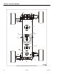
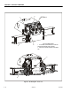
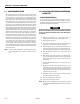
DETAIL A
DETAIL B
4
6
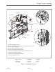
11,12,A,G
10
11,12,B,G
11,12,C,G
11,12,E,G
11,12,D,G
11,12,F,G
2
A - Assemble to Axle Box Mid Plate; Typical 8 Places
B- Asse mbl e to Top Pl at e o f A xl e B oxe s; Ty pi ca l 4 Plac es ; Torq ue ; S elec t a pp ro pr ia te bo lt to ens ur e 0 .5 ±0 .062
inches (12.7 ± 1.587 mm) thread engagement.
C - Assemble to Side Plates of Axle Weldments; Typical 16 Places.
D - Assemble to Front and Rear Plates of Axle B ox es ; Typical 8 Place s.
E - Assemble to Top Plate of Axle Weldment; Typical 4 Places; Torque; Select appropriate bolt to ensure 0.5
±0.062 inches (12.7 ± 1.587 mm) thread engagement.
F - Assemble to Bottom Plate of Axle Box Weldment; Typical 8 Places.
G - See Axle Stop Shimming Procedure on Sheet 1
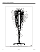
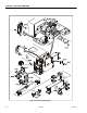
1. Axle Oscillation Cylinder
2. Axle
3. Axle Powertrack
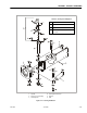
4. Extension Cylinder
5. Axle Pivot Pin
6. Axle Limit Switch
7. Axle Stop Pin
8. Rubber Pad
9. Hose Clamp
10. Stop Block
11. Wear Pad
12. Shim
Figure 3-10. Oscillating Axle - Sheet 2 of 2