
Service Manual Manual

SECTION 6 - JLG CONTROL SYSTEM
6-110 – JLG Lift – 3121142
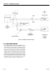
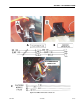
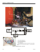
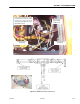
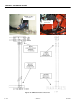
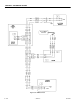
Figure 6-27. CANbus Connections - Sheet 2 of 5
1. Chassis Module CANbus Link
2. Ground Module CANbus Link
3. Boom Length & Angle Module
4. BLAM J1 (Gray) Plug
* Remove BLAM J1 Plug and measure the A & B pin of the T fitting.
This should measure approximately 60 Ohms for a complete CANbus
Circuit.