
Service Manual Manual

SECTION 6 - JLG CONTROL SYSTEM
6-42 – JLG Lift – 3121142
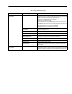
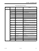
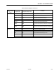
MOMENT: Displayed if MODEL NUMBER = 7 or 8
(LB-IN) ACTUAL XXXXXXXX Displays current moment value
(LB-IN)
OVER
XXXXXXXX Displays current over moment setpoint.
(LB-IN)
UNDER
XXXXXXXX Displays current under moment setpoint.
CAL PT
UNDER
XXXXXXXX Displays the under moment value recorded during boom sensor calibration.
CAL PT
WIT YEL
XXXXXXXX Displays the yellow witness mark moment value recorded during boom sen-
sor calibration.
CAL PT
WIT GRN
XXXXXXXX Displays the green witness mark moment value recorded during boom sensor
calibration.
CYL PIN
RATIO
X.XXX Displays the current cylinder moment pin ratio of X and Y forces.
PIN
E FLAGS
0xXXXX Displays the current error flag status of the cylinder moment pin.
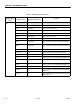
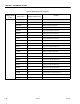
SKY WELDER YES/NO Displays the status of Sky Welder selected during boom sensor calibration.
(Displayed if MODEL NUMBER = 7 or 8)
SKY CUTTER YES/NO Displays the status of Sky Cutter selected during boom sensor calibration.
(Displayed if MODEL NUMBER = 7 or 8)
SKY GLAZIER YES/NO Displays the status of Sky Glazier selected during boom sensor calibration.
(Displayed if MODEL NUMBER = 7 or 8)
SKY BRIGHT YES/NO Displays the status of Sky Bright selected during boom sensor calibration.
(Displayed if MODEL NUMBER = 7 or 8)
PIPE RACKS YES/NO Displays the status of Pipe Racks selected during boom sensor calibration.
(Displayed if MODEL NUMBER = 7 or 8)
CAMERA MOUNT YES/NO Displays the status of Camera Mount selected during boom sensor calibration.
(Displayed if MODEL NUMBER = 7 or 8)
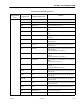
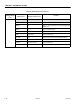
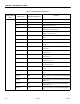
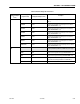
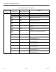
Table 6-5. Machine Diagnostics Parameters
Diagnostics Submenu
(Displayed on Analyzer
1
st
Line)
Parameter (Displayed on
Analyzer 2
nd
Line)
Parameter Value
(Displayed on Analyzer 2
nd
Line)
Description