
Service Manual Manual

SECTION 3 - CHASSIS & TURNTABLE
3121142 – JLG Lift – 3-77
Motor Control Valve Assembly
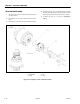
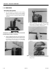
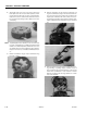
1. Lay assembly down with motor ports facing up. Remove
the two plastic plugs in the motor ports, being careful
not to loose the O-ring in each port. Assemble the Motor
control Valve (32) onto the Motor (10) with Bolt (34) and
Lock Washers (33). Torque Bolts (33) 23 to 27 ft-lbs. (32 to
38 Nm).
NOTE: Be sure to align the holes in the control valve with the
motor ports.
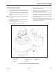
2. Install Elbow Fittings (36) into Brake (26) and torque 13
to 15 ft-lbs. (18 to 21 Nm).
3. Install Elbow Fittings (36) into Motor Control Valve (32)
and torque to 13 to 15 ft-lbs. (18 to 21 Nm).
4. Assemble Tube (35) into Elbow Fittings (36) and torque
13 to 15 ft-lbs. (18 to 21 Nm).
5. Install O-ring Plugs (21) into Motor Control Valve (32)
and torque 30 to 31 ft-lbs. (42 to 43 Nm).
6. Pressure test brake, tube and control valve connections
by applying 3000 psi (207 bar) pressure to the brake
bleed port and holding for 1 minute. Check for leaks at
the control-valve-motor interface and the tube connec-
tions. Release pressure.
7. Place I.D. Plate (24) onto Housing (1G) with two Drive
Screws (25). I.D. Plate (24) is to be inline with O-ring Plug
(1J) as shown on assembly print.
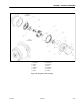
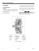
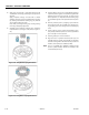
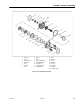
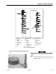
1J. O -R in g P lug
10. H yd ra ul ic M oto r
21. Plug
24. ID Plat e
25. D ri ve S crew
26. Hyd ra ul ic Br ak e
32. Motor Control Valve
33. Lo ck wa sh er
34. Hex Bolt
35. Hyd ra ul ic Tubin g
36. El bo w
Figure 3-46. Swing Drive - Motor Control Valve Assembly