
Parts Manual Owner's manual

3-24 1200SJP 1350SJP 3121208
SECTION 3 BOOM
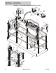
34 4 Sensor, Angle Indicator Options: (Note: Control System must be
recalibrated when Sensor is replaced)
Use 1001147479 Prior to SN 0300141600 (was p/n 4360534 & p/n 4360545)
Use 1001133329 SN 0300141600 to SN 0300157203 (was p/n 4360545)
1001133329 SN 0300157203 to Present
35 4460914 2 Terminal, Base
36 4711400 10 Flatwasher 1/4in Thin
37 4711600 2 Flatwasher 3/8in Thin
38 4891400 4 Flatwasher 1/4in Hardened
39 0641406 4 Bolt 1/4in-20NC x 3/4in
40 4460428 2 Connector, Strain Relief
41 4846484 1 Mount, Switch
42 1 Pad, Rubber Options:
3340861 Prior to SN 0300132905
3340941 SN 0300132905 to Present
43 1705366 1 Decal - Boom Length (500LB Cap)
44 Use 3574616 1 Plate, Boom Length (was p/n 3573503)
45 4240032 2 Tie-Strap (Prior to SN 0300088626)
46 Not Used 6 Screw 5/16in-18NC x 1in
47 1705367 1 Decal - Boom Length (1000LB Cap)
48 4460968 3 Connector, Strain Relief (Not Shown)
49 1320136 2 Clamp, Cable (Not Shown)
50 4341158 2 Plate, Mounting Sensor (SN 0300088626 to Present)
51 8310070 6 Pushnut 3/8in (SN 0300088626 to Present)
52 6 Screw Options:
0791604 Screw 3/8in-16NC x 1/2in (Prior to SN 0300088626)
0791605 Screw 3/8in-16NC x 5/8in (SN 0300088626 to Present)
53 0100081 AR Adhesive (SN 0300132905 to Present)
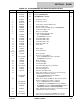
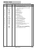
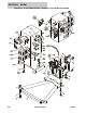
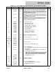
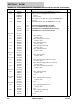
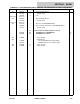
FIGURE 3-5. BOOM SENSORS AND SWITCHES INSTALLATION (CONTINUED)
ITEM # PART NUMBER QTY. DESCRIPTION REV.