
Service Manual Instruction Manual

SECTION 3 - CHASSIS & TURNTABLE
3-14 – JLG Lift – 3121171
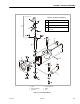
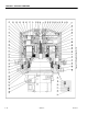
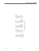
3.10 OSCILLATING AXLE SYSTEM
The oscillating front axle is attached to the frame by a pivot
pin, which allows all four wheels to remain on the ground
when traveling on rough terrain. The oscillating axle also
incorporates two lockout cylinders connected between the
frame and the axle. The lockout cylinders permit axle oscilla-
tion when the boom is in the transport position (see Section
4.2, Transport Position Sensing System) and drive is com-
manded.
The lockout cylinders will lock and hold the axle when drive is
not commanded or when the boom is outside the transport
position. The cylinders unlock when pilot pressure is applied
to the holding valves mounted on the cylinders and lock when
pilot pressure is removed. Pilot pressure is available from brake
pressure and is controlled by a solenoid operated lockout
valve mounted in the frame. To ensure the lockout valve is
functioning correctly, a NO pressure switch is mounted
between the lockout valve and the holding valves. The system
is “healthy” when pressure trips the pressure switch when the
lockout valve is energized and conversely is healthy when the
lack of pressure resets the pressure switch when the lockout
valve is de-energized.
Failures in the oscillating axle system will cause the control
system to disallow main boom lift up and telescope out, and
tower boom lift up when both booms are within the transport
position and will disallow drive/steer, lift up and telescope out
when either boom is beyond the transport position.
NOTE: For more detailed information concerning system adjust-
ment and operation, refer to Section 6 - JLG Control Sys-
tem.
3.11 OSCILLATING AXLE BLEEDING PROCEDURE AND
LOCKOUT TEST
Lockout Cylinder Bleeding
To start the test, the axle must be fully oscillated in one direc-
tion. Start with oscillating the axle so that the left lock-out cyl.
is fully retracted (left front tire up), and the right lock-out cyl. Is
fully extended (right front tire down).
ENSURE PLATFORM IS FULLY LOWERED AND BOOM IS CENTERED OVER REAR
AXLE PRIOR TO BEGINNING BLEEDING PROCEDURE. MAKING SURE MACHINE
IS ON A LEVEL SURFACE AND REAR WHEELS ARE BLOCKED, BRAKE WIRE IS
DISCONNECTED.
1. Making sure machine is on a level surface and rear
wheels are blocked, machine is in transport mode.
2. Disengage the drive hubs.
3. Use suitable container to catch any residual hydraulic
fluid, place container under the lockout cylinder.
4. With the left lockout cyl. retracted, open the bleeder on
top of the cylinder, then have an operator from the plat-
form (on high engine) feather drive. Activate drive fully.
5. Close the bleeder when there is a steady stream of oil
and not air.
6. With the axle in the same position, go to the right lock-
out cyl. and open the bleeder at the rod end. Activate
drive in the same manner and close when all air has
been purged.
7. Close the bleeder when there is a steady stream of oil
and not air.
8. Oscillate the axle the other direction, left lock-out cyl.
extended (tire down), right lock-out cyl. retracted (tire
up). Use the same procedure for the bleeder in the rod
end of the left lock-out cyl., Then the piston end of the
right lock-out cyl. then close.
9. Repeat this process one more time to ensure that all air
has been purged from the system.
10. Perform oscillating axle lockout test.
11. If necessary, repeat steps 1 thru 9.
NOTE: Bleeding of the oscillating axles is an infrequent operation
performed after hydraulic line failure and or lock-out cylin-
der repair.