
Service Manual Instruction Manual

SECTION 6 - JLG CONTROL SYSTEM
3121171 – JLG Lift – 6-125
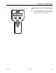
Load Moment Pin Troubleshooting
The following Troubleshooting Charts outline diagnostic mea-
sures to be taken to diagnose problems within the Load
Moment Pin portion of the JLG Control System. If necessary,
refer to Section 4 for information concerning replacement of
the Load Moment Pin.
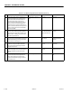
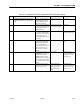
Table 6-11. Load Moment Pin Troubleshooting: Can Communications Lost
STEP FAULT CODE/SYMPTOM REPAIR YES NO
1 6/6 CYLINDER LOAD PIN CAN COMMUNICA-
TIONS LOST
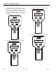
Check for correct and tight
wire connections at the
deutsch and phoenix con-
nectors of the Load Sensing
Pin harness and perform a
continuity check.
Go to step 2 Replace harness.
(4922826)
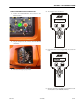
2 Check for loose pins in the
potting of the Boom Length
& Angle Module J4 connec-
tion.
Replace the BLAM &
Perform the Boom Sen-
sor calibration process.
Go to ste p 3
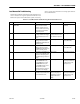
3 Inspect the CANbus link ”T”
fitting connections at the
BLAM & Ground Module. Are
the fittings dry?
Go to step 4 Replace ”T” fitting con-
nector. (4460945)
4 Inspect the CANbus link ”T”
fitting connections at the
BLAM & Ground Module. Per-
form a continuity check.
Go to step 5 Replace ”T” fitting con-
nector. (4460945)
5 Check the J1 and J4 plug con-
nections on the BLAM, make
sure the notched plugs line
up with the plug sockets cor-
rectly.
Go to step 6 Position plug correctly.
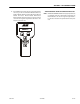
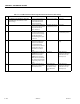
6 Use the Analyzer, scroll – + to
the DIAGNOSTICS menu,
press ENTER, then scroll to
the MOMENT menu, and
press ENTER, check to see i f
Actual / Over / Under
moment values are register-
ing on the screen display.
Go to step 6 Replace the load
moment pin. & Perform
the Boom Sensor cali-
bration process.
7 If they are, try boom sensor
calibration to see if the values
come within the chart.
If the problem still
exists, verify steps 1-7
again before contact-
ing the JLG Service
Dept.
Replace the load
moment pin. & Perform
the Boom Sensor cali-
bration process.