
Service Manual Instruction Manual

SECTION 6 - JLG CONTROL SYSTEM
6-120 – JLG Lift – 3121171
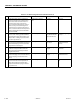
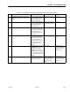
Table 6-9. Troubleshooting: BLAM Can Communications Lost
STEP ACTION REQUIRED SPEC YES NO
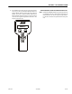
1 Install the Analyzer at the ground station,
scroll to the ”Diagnostics” sub level menu,
press ”enter” then scroll to the ”Versions”
menu item press ”enter” and view the
screen, reference the Diagnostics / Version
Chart to assist you in determining which
module has lost it’s communication link. In
some cases the module that shows up with a
question may be defective if all other CAN-
bus links check OK.
See Diagnostics / Version
Chart
See step 2 See step 2
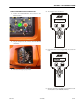
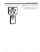
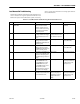
2 Disconnect the BLAM J 1 deut sche pl ug co n-
nection at the "T” fitting just above the fuel
tank. Perform an ohms check at the ”A” and
”B” pins of the "T” fitting. Inspect the shield
wire ”C” for possible short.
Approximately 60 ohms. CANbus circuit is com-
plete.
BLAM suspected defec-
tive.
Reconnect plug and go
to step 3
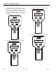
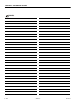
3 Disconnect the Ground Module deutsche
plug from ”T” fitting at the BLAM above the
fuel tank. Perform an ohm check at the ”A”
and ”B” sockets of the deutsche plug. Inspect
the shield wire ”C ” for possible short.
Approximately 120 Ohms Reconnect harness and
go to ste p 4
Repair or replace the
Ground Module to
BLAM harness.
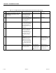
4 Verify the CANbus link signal wires are
installed correctly at the "T” fitting at the
Ground Module.
Electrical Schematic Reconnect plug and go
to step 5
Wire per Electrical
Schematic
5 Verify the lift cylinder load moment harness
has good continuity and wired correctly at
the J4 plug on the BLAM.
Continuity Reconnect plug and go
to step 6
Repair or replace Chas-
sis Module harness.
6 Disconnect the Chassis Module plug con-
nection at the battery and perform an ohm
check at the #1 and #2 socket of the deutsche
plug. Inspect the shield wire #3 for possible
short.
Approximately l 20 Ohms Reconnect plug and
stop
Inspect harness and
connections to the
Chassis Module.