
Service Manual Instruction Manual

SECTION 6 - JLG CONTROL SYSTEM
3121171 – JLG Lift – 6-115
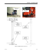
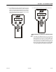
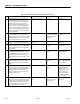
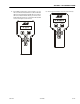
9 Disconnect the Chassis Module deutsche
plug at the ”T’ fitting below the Boom
Length & Angle Module. Perform an ohms
check at the ”A” and ”B” sockets of the
deutsche plug. Inspect the shield wire ”C” for
shorts.
Approximately 120 ohms Reconnect deutsche
plug and go to step 10
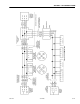
Inspect the harness
from the ”T” fitting at
the BLAM to the Chas-
sis Module plug con-
nection at the battery.
Assure proper continu-
ity and correct wiring
per Electrical Sche-
matic.
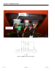
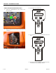
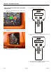
10 Disconnect the Chassis Module connection
at the right side of the battery at the turnta-
ble lock pin. Perform an ohms check at the #1
and #2 connections of the plug. Inspect
shield wire #3 for possible short.
Approximately 120 ohms Reconnect plug and go
to step 11
Inspect the harness
fro m th e sl ip r ing con-
nections at the top and
bottom plug connec-
tions of the swivel.
Assure proper continu-
ity and correct wiring
per Electrical Sche-
matic.
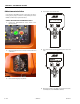
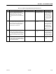
11 Disconnect the Chassis Module connection
below the swivel under the machine. Per-
f or m an o hm s ch e ck a t t h e # 1 an d #2 c on n ec -
tions of the plug that is routed to the Chassis
Module. Inspect shield wire #3 for possible
short.
Approximately 120 ohms Reconnect plug and go
to step 12
Inspect the harness
from the bottom of the
swivel into the Chassis
Module. Assure proper
continuity and wiring r
schematic 1870149A.
12 Make sure the Chassis Module CANbus link
wires are installed correctly at the plug near
the battery, the plug below the swivel and 31
plug at the Chassis Module.
Electrical Schematic Stop Replace the Chassis
Module.
Table 6-8. Troubleshooting: Platform Can Communications Lost
STEP ACTION REQUIRED SPEC YES NO