
Service Manual Instruction Manual

SECTION 6 - JLG CONTROL SYSTEM
6-114 – JLG Lift – 3121171
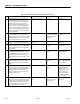
Table 6-8. Troubleshooting: Platform Can Communications Lost
STEP ACTION REQUIRED SPEC YES NO
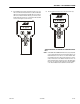
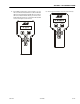
1 Install the Analyzer at the ground station,
scroll to the ”Diagnostics” sub level menu,
press ”enter” then scroll to the ”Versions”
menu item press ”enter” and view the
screen, reference the Diagnostics / Version
Chart to assist you in determining which
module has lost it’s communication link. In
some cases the module that shows up with a
question may be defective if all other CAN-
bus links check OK.
See Diagnostics / Version
Chart
See step 2 See step 2
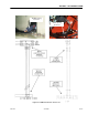
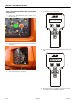
2 Disconnect the Ground Module J7 deutsche
plug connection at the "T" fitting inside of
the ground control station. Perform an ohms
check at the ”A” and ”B” pins of the "T" fitting.
Inspect the shield wire ”C” for shorts.
Approximately 60 ohms. CANbus circuit is
complete. Platform
Module suspected
defective
Reconnect plug and go
to step 3
3 Make sure the CANbus link wires are
installed correctly at the Platform Module.
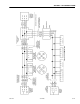
See Electrical Schematic in
Section 7
Go to step 4 Wire per Electrical
Schematic
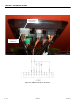
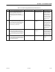
4 Disconnect the platform cannon plug and
ground cannon plug that holds the CANbus
link. Red (3) Black (2) and Shield (1) perform a
continuity test.
Continuity Reconnect plug and go
to step 5
Repair or replace plat-
form harness.
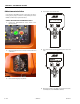
5 Disconnect the deutsche plug connection
from the Platform Module at the ”T” fitting
inside of the ground station. Perform an
ohms check at the ”A” and ”B” sockets of the
deutsche plug. Inspect the shield wire ”C” for
shorts.
Approximately 120 ohms. Reconnect plug and go
to step 6
Suspected defective
Platform Module.
6 Inspect the Platform Module harness con-
nection at the ground cannon plug and at
the ”T”’ fitting inside of the ground control
station.
Continuity Reconnect harness and
go to ste p 7
Repair or replace har-
ness inside the ground
control station.
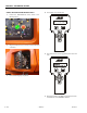
7 Disconnect the deutsche plug connection
from the Boom Length & Angle Module at
the ”T’ fitting inside of the ground station.
Perform an ohms check at the ”A” and ”B”
sockets of the deutsche plug. Inspect the
shield wire ”C” for shorts.
Approximately 120 ohms Reconnect plug and go
to step 8
Verify step 7, inspect
the BLAM to Ground
Module harness con-
nection s at both ”T" fit-
ting connections for
proper continuity and
correct wiring per Elec-
trical schematic.
8 Disconnect all deutsche plug connections at
the "T” fitting in the ground station and the
BLAM, perform a continuity test on all ”A” ”B”
and ”C” pins use the singular end of the fit-
ting and cross probe the corresponding let-
ters of the other two connections.
Continuity (NO OHM VAL-
UES)
Reconnect all deutsche
plugs at the "T” fitting
and go to step 9
Replace defective ”T"
fitting plug.