
Service Manual Instruction Manual


SECTION 3 - CHASSIS & TURNTABLE
3-4 – JLG Lift – 3121171
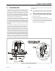
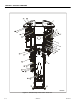
4. Ensure the arm will clear the axle (without bottoming
out to 70° stroke of the switch) in the retracted position.
5. Check for proper operation. Axle set light is to deacti-
vate when the axle is retracted 0.625 inches (16 mm)
maximum from fully extended.
3.4 DRIVE SYSTEM
The drive system utilizes 2 traction pumps so each side is pow-
ered individually. This produces maximum tractive effort to
wheels by minimizing flow divider losses. The maximum drive
speed is modulated with the steered angle of the wheels to
eliminate the whiplash effect of driving at full speed and maxi-
mum steering lock.
3.5 STEERING CONTROL SYSTEM
Each wheel is individually steered by means of a closed circuit
control system utilizing a steer sensor on each wheel, 4 steer
cylinders, and proportional valves.
The control system senses the wheel position in relation to the
steering command (direction and steering mode) and auto-
matically synchronizes the movement of all 4 wheels to the
desired position.
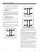
There are three different modes of steering selectable by the
position of the steer select switch on the platform control
panel: conventional two wheel steering, crab and coordinated.
These are shown below.
Each wheel has its own steer cylinder, wheel angle sensor, and
proportional valve, allowing the control system to position
each wheel to the ideal angle for all steering modes and all
steering commands.
Changes in steering modes while the footswitch is depressed
causes the wheels to automatically adjust to the appropriate
angle for the selected steering mode based on the position of
the inside front wheel. If the steer select switch is changed
without the footswitch being depressed or when the EMS is
off, the wheels will not move until the footswitch is depressed
and a steering or drive command has been initiated.
The steering angles are limited to ±25 degrees anytime the
axles are not fully extended. See the Axle Extension System
(see Section 3.2, Axle Extension System) for interaction with
the axle extension system.
If a wheel cannot achieve its commanded angle within a spec-
ified time, it is considered jammed. When a wheel is consid-
ered jammed during steering, a fault is reported and the
remaining wheels will continue to their commanded position.
The fault is cleared when the footswitch is cycled.
If a wheel is jammed making it significantly out of position,
with regard to the other wheels, the drive motors are
restricted to their maximum displacement (slow speed).
Wheel angle sensor failures will result in an approximated
steering control logic that will allow the operator to move the
Figure 3-2. Conventional Two Wheel Steer Mode
Figure 3-3. Crab Steer Mode
Figure 3-4. Coordinated Steer Mode