
Service Manual Instruction Manual


SECTION 3 - CHASSIS & TURNTABLE
3121171 – JLG Lift – 3-3
3.2 AXLE EXTENSION SYSTEM
The Axle Extension System allows each of the four axles to be
extended and retracted together while maintaining full steer-
ing control as the machine is driven. The system allows the
axles to extend or retract only while the boom is in the trans-
port position (see Section 4.2, Transport Position Sensing Sys-
tem) and in order to minimize wheel scrubbing during axle
movement, a minimum drive speed must be attained before
axle extension/retraction will be permitted.
To extend/retract the axles, the user engages the axle extend/
retract switch on the platform console and the drive control at
the same time. The axle set indicator will be off when the axles
are not fully extended and the axle extend/retract switch is
not engaged. It will flash while the axles are extending or
retracting and will be on constantly when the axles are fully
extended.
The system uses four limit switches (one at each axle) to sense
when the axles are fully extended. If any of the switches are
not made, the control system considers the axles retracted.
With the axles not fully extended, the boom is restricted to
operation within the transport position (see Section 4.2, Trans-
port Position Sensing System). If a signal from any axle extend
sensing switch is lost when the boom is beyond the transport
position, the axle set indicator will flash and drive/steer func-
tions will be disabled until the boom is brought back into the
transport position. The steering angle will be automatically
limited to ± 25 degrees anytime the axles are not fully
extended. If the wheel angle is more than ± 25 degrees when
the axle retract command is engaged, the control system will
automatically reduce the wheel angle to 25 degrees during
axle retraction.
NOTE: For more detailed information concerning system adjust-
ment and operation, refer to Section 6 - JLG Control Sys-
tem.
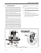
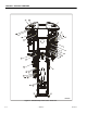
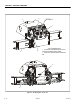
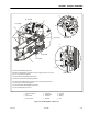
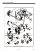
3.3 AXLE LIMIT SWITCH ADJUSTMENT PROCEDURE
1. Fully extend the axles.
2. Initially position the limit switch arm straight.
3. Select the mounting plate bolt pattern to position the
switch roller within 0.125 inches (mm) from the edge of
the axle cutout. It may be necessary to reposition the
switch arm ±10° to accomplish this.
Figure 3-1. Axle Limit Switch Adjustment