
Service Manual Instruction Manual

SECTION 6 - JLG CONTROL SYSTEM
3121171 – JLG Lift – 6-63
2. After pressing the ENTER key , the Control System
will verify the measured angle of the tower cylinder
matches the target angle of 74.6 +/-0.5 (relative to the
turntable), otherwise, the analyzer will display “CAL
FAILED” on the top line and “TWR UP TO STOP” or
“TOWER DWN TO STOP” on the bottom line each time
the ENTER key is pressed and the measured angle does
not match the expected angle. If the target is reached,
the analyzer will display “CAL POSITION 8” on the top
line and “CALIBRATING…”on the bottom line and calcu-
late the load pin cal resultant force 8, load pin cal force
vector angle (ref t/t base plate), and the calculated cylin-
der angle at load pin cal point. The Control System will
calculate the required rotation correction angle of the
load pin cal force vector angle to match the cylinder
angle at the load pin cal point. The control system will
modify the load pin x and y values into x’ and y’ values
for use in determining moments by rotating the forces
by the rotation correction angle and redistributing the
forces onto the new axis. The control system shall calcu-
late the corrected load pin cal moment 8. The Control
System will also verify the calculated rotational correc-
tion angle is +/- 10 degrees. If it falls outside of this toler-
ance, the Control System will fail calibration and the
analyzer will display “PIN ANGLE FAULT”.
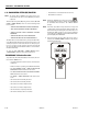
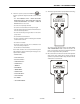
Step 9 - Position 9
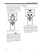
1. After completing the previous step, the analyzer will
read:
The Control System will disallow all functions except
auto platform level and swing.
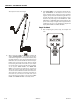
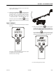
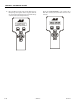
Swing turntable 180° - The turntable must be centered
over the original end of chassis