
Service Manual Instruction Manual

SECTION 6 - JLG CONTROL SYSTEM
6-60 – JLG Lift – 3121171
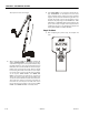
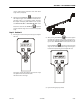
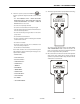
Telescope tower out to max length
2. After pressing the ENTER key , the analyzer will
display “CHECKING BOOM…” and capture the position
of the Tower Length. The control system will then, Keep
the PVG command at zero leave the Main Control and
PVG enable valves off and Turn On the Tower Telescope
Enable valve and monitor the Tower Telescope length
for decreasing movement of more than 0.5" (1.27 cm) for
60 seconds. If this occurs the test will abort and display
on the top line “CHECK FAILED:” and “TOWER TELE
HOLD” on the bottom line. After the 60 seconds has
elapsed the control system will leave the Enable valve
on and turn on the Main Control Valve and monitor the
Tower Telescope length for decreasing movement of
more than 0.5" (1.27 cm) for 60 seconds. If this occurs
the test will abort and display on the top line “CHECK
FAILED:” and “TOWER TELE APU” on the bottom line.
3. If the “CHECK BOOM…” test passes the analyzer will dis-
play “CALIBRATING…”on the bottom line and record
tower extended length 1 (upper) and tower extended
length 2 (lower). The tower extended length will be set
at 669.4”. The length 1 sensor and the length 2 sensor
must be in the proper range or “CAL FAILED” and “TWR
LEN1 FAULT” or “TWR LEN2 FAULT” will be displayed. The
precise tower transport length switch trip point will be
verified to be 4.0”+3.5”/-1.5”, otherwise the analyzer will
display “CAL FAILED” and “TWR L SW FAULT”.
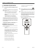
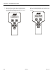
Step 6 - Position 6
1. After completing the previous step, the analyzer will
read: