
Service Manual Instruction Manual

SECTION 6 - JLG CONTROL SYSTEM
6-56 – JLG Lift – 3121171
• “CAL STEERING”
•“CAL TILT SENSOR”
• “SELECT GRND MODE”
The analyzer will then prompt with “UNLOAD PLAT-
FORM?”, “LEVEL PLATFORM?”, “CENTER PLATFORM?”, “JIB
UP TO MAX?”, “MAIN DWN TO MIN?”, “TWR DWN TO
MIN?”(control system energizes tower lift down and
tower tele in with tower lift down commands), “TWR IN
TO MIN?”(control system energizes tower lift down and
tower tele in with tower lift down commands) to ensure
the machine is set up in the proper position for Calibra-
tion Step 1.
2. Once the initial conditions are verified, the analyzer will
display “SKY WELDER YES”. If a sky welder is not installed,
press an ARROW key to switch to “SKY WELDER NO. A
similar set of menus will prompt selection of Sky Cutter,
Sky Glazier, Sky Bright, Pipe Racks and Camera Mount. If
Sky Bright is selected, the analyzer will display “CAL
FAILED” and “REMOVE SKYBRIGHT”. If more then one
accessories is selected except for the combination of Sky
Welder/Sky Cutter the analyzer will display “CAL FAILED”
and “# OF ACCESSORIES”. If a valid accessory option has
been selected after the camera mount selection and the
operator presses the ENTER key , the analyzer will
display “CALIBRATE?” on the bottom line.
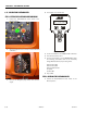
3. After pressing the ENTER key , the analyzer will
read:
If there is a fault in the configuration process “CAL
FAILED” and “MAIN ANGL1 FAULT” or “MAIN ANGL2
FAULT” will be displayed. The Control System will then
record right main boom min angle, left main boom min
angle, retracted tower length 1 (upper), retracted tower
length 2 (lower) and low cylinder angle. The main boom
min angle will be set at –4.2 (ref tower). The low cylin-
der angle will be set to 1.0. The tower retracted length
will be set at 305.4” (775.7 cm). The right main boom
angle sensor reading must be within 5 and 25 and the
left main boom angle sensor reading must be within
155 and 175 or “CAL FAILED” and “MAIN ANGL1
FAULT” or “MAIN ANGL2 FAULT ” will be displayed. The
length 1 sensor and the length 2 sensor must be within
range or “CAL FAILED” and “TWR LEN1 FAULT” or “TWR
LEN2 FAULT” will be displayed. The cylinder angle read-
ing must be within range or “CAL FAILED” and “CYL
ANGL FAULT” will be displayed.
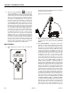
Step 2 - Position 2
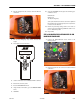
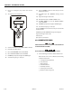
1. After completing the previous step, the analyzer will
read:
The Control System will disable all functions except auto
platform level and main lift up. The Control System will
energize main lift up, tower lift down and tower tele in
with the main lift up command until the main boom
transport angle limit switch is tripped. The analyzer will
display “CAL FAILED” and “TWR NOT IN” if movement of
either tower length sensors is detected or “TWR NOT
DWN” if movement of the cylinder angle sensor is
detected. The Control System will monitor and record
the main boom angle reading at which the main boom
transport angle limit switch is tripped (see position 6 for