
Service Manual Instruction Manual

SECTION 5 - HYDRAULICS
5-52 – JLG Lift – 3121171
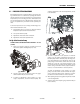
Adjustments Made at the Frame Valve Bank
AXLE EXTEND AND RETRACT, FRONT AND REAR - 2500 PSI
(172.3 BAR)
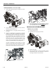
1. To extend the axles, drive the machine back and forth
until extended. A machine that cannot be driven must
be jacked up.
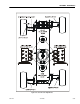
2. On both the front and rear frame valve banks, install a
high pressure gauge on ports MA1 for extend and MA2
for retract. The gauge should read 2500 psi (172.3 Bar) in
both directions.
3. The axle extend/retract cylinders are connected hydrau-
lically in parallel. In order to get the correct pressure of
the circuit being adjusted, unscrew the solenoid coil
from the circuit not being adjusted and pull it away from
the valve.
4. Turn clockwise to increase, counterclockwise to
decrease.
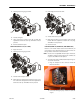
STEERING, FRONT AND REAR
NOTE: The following procedure requires 2 people to perform. One
is needed for verifying / adjusting pressure readings and
wheel spindle alignment the other for operating the steer
functions and using the Analyzer from the platform.
The Analyzer is required to perform the pressure check proce-
dure through access of the calibration menu. The calibration
menu will allow for extending and retracting the steer cylin-
ders individually, verifying pressures, and proper steer sensor
calibration. Verification of the steer sensor calibration will
require one of two types of measuring methods; using a
square and ruler or using string as explained in Section 6 - JLG
Control System. The purpose of these measuring tools is to
assure that the wheel spindle is aligned “straight” with the
extended axle weldment.
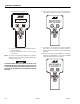
1. Position the machine with both front and rear axles fully
extended.
2. Install the Analyzer in the platform control box and scroll
menu’s to Access Level 2 and insert password (33271) to
get into Access Level 1.
3. Scroll to the calibration mode. Once in the calibration
mode, press “ENTER” and scroll to steer. Once in the
steer calibration mode, the Analyzer is going to ask to
calibrate the steer sensors, this is going to allow extend-
ing and retracting each steer cylinder individually dur-
ing this process. The JLG control system will ask to
calibrate the left front sensor, the left rear sensor, the
right front sensor and finally the right rear sensor in that
order. During this calibration mode each individual steer
cylinder will be extended and retracted to verify correct
pressures with the marked MS (Measure Steer) ports on
the steer / axle valve that pertains to that steer cylinder.
Refer to the Hydraulic Schematic in Section 7 - Schemat-
ics.