
Service Manual Instruction Manual

SECTION 5 - HYDRAULICS
3121171 – JLG Lift – 5-51
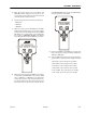
5. When the operator enters access code 146005, "SET
PRESSURES" will be displayed on the top line and cur-
rent sub-menu on the bottom line. The sub-menus will
scroll with the left and right arrow keys.
6. Pressure setting sub-menus will include the following:
•"MAIN LIFT?"
•"TWR LIFT?"
•"TWR TELE?"
7. When the operator presses the ENTER key, "SET PRES-
SURES" will be displayed on the top line of the analyzer
and the bottom line will display the following: "WARN-
ING" flashed on a 0.5 hertz rate for 3 cycles followed by
the scrolling of "MOVEMENT POSSIBLE". This flashing
and scrolling will repeat until the ENTER key is pressed.
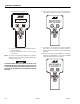
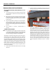
8. When the operator pressed the ENTER key, the control-
ler will display "SET PRESSURE" on the top line, "MAIN
LIFT" or "TWR LIFT" or "TWR TELE" on the bottom line
and will allow operation of the selected submenu func-
tion with the enable valve closed. If movement of any of
the three functions is detected, the controller will dis-
play "SERVICE FAILED" on the top line and "VALVE FAULT"
on the bottom line as shown below.
9. Pressing the ESCAPE or the ENTER key once will revert
back to the pressure setting sub-menus ("MAIN LIFT",
"TWR LIFT", "TWR TELE").
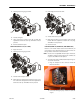
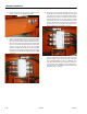
10. Select the PVG function then use the toggle switches at
ground control to energize function. Pressure should be:
• Main Lift UP - 2755 to 3088 psi (190 to 213 Bar)
• Main Lift DN - 2755 to 3088 psi (190 to 213 Bar)
• Tower lift UP - 2755 to 3088 psi (190 to 213 Bar)
• Tower Lift DN - 2755 to 3088 psi (190 to 213 Bar)
• Tower Tele OUT - 2537 to 2871 psi (175 to 198 Bar)
• Tower Tele IN - 2537 to 2871 psi (175 to 198 Bar)