
Service Manual Instruction Manual

SECTION 5 - HYDRAULICS
3121171 – JLG Lift – 5-45
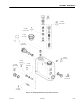
5.6 ENABLE VALVES
Removal
1. Make sure the machine is on a firm level surface.
2. Extend the axles until the axle locked light is illumi-
nated.
3. Position the machine with the booms on suitable boom
rests.
4. Shut off the engine; remove the key and tag out the
machine.
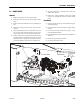
5. Locate and identify the three enable valves on the left
side of the machine. Mark the function that the valve
controls on the valve, i.e. tower lift, tower tele, main lift.
6. Position a drain pan to catch any hydraulic spills and tag
and disconnect the hydraulic hoses going to the three
enable valves. Cap or plug all hoses to prevent contami-
nation of the hydraulic system and loss of hydraulic oil.
7. Tag and disconnect the electrical harness from each
enable valve solenoid.
8. Remove the existing hardware securing the enable
valves to the turntable and remove the three enable
valves.
Installation
1. Install the enable valves onto the turntable using the
mounting hardware.
2. Connect all hoses and electrical lines as tagged during
removal.
3. If coils were removed, reinstall and torque to 5 foot
pounds (6.8 Nm) maximum.
4. Check the hydraulic oil level in the tank and replenish as
necessary.
5. Remove the tag out from the machine.
6. Proceed to next test procedure.
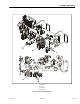
MAIN LIFT ENABLE
TOWE R LIFT ENA BLE
TOWER TELE ENABLE
Figure 5-49. Enable Valves