
Service Manual Instruction Manual

SECTION 5 - HYDRAULICS
5-24 – JLG Lift – 3121171
5.3 COUNTERBALANCE VALVE CHECK
1. Position the machine on a firm level surface.
2. Ensure the tower boom and main booms are on their
respective boom rests.
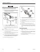
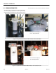
3. Swing the turntable to the side about 35-45° to gain
access to the counterbalance valve.
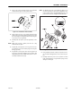
4. Access the Tower Lift Cylinder Counterbalance Valve
through the access hole in the bottom plate of the turn-
table.
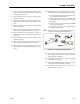
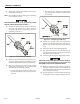
5. Torque the counterbalance valve 45 to 50 foot pounds
(61 to 68 Nm) and take note of how much the counter-
balance valve moves.
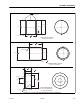
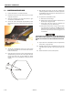
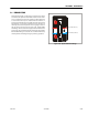
6. If the valve moves less than 0.125" (3 mm) radially (see
example below), proceed to the next step. If the valve
moves more than 0.125" (3 mm) radially (see sketch
below), replace the counterbalance valve, proceed to
Step #8.
7. After applying the torque to the valve, examine the
valve for hydraulic oil leaks. If the valve leaks, replace the
counterbalance valve, see Step #10. If the valve does not
leak, proceed to Step #13.
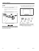
8. To replace the counterbalance valve:
a. Remove the valve cartridge.
b. Examine the removed cartridge for completeness of
the valve, the o-rings and seals.
c. If the valve, seals and o-rings are complete and
accounted for, proceed to the next step.
d. If any portion of the valve, o-rings or seals are miss-
ing, quarantine the machine. Do NOT allow the
tower boom to be raised. Contact a certified service
technician and make sure the missing parts are
accounted for.
IF THE CARTRIDGE REQUIRES REPLACEMENT, THE PORT IN THE VALVE BLOCK
MUST BE FREE OF RESIDUAL HYDRAULIC OIL BEFORE INSTALLING THE NEW
CARTRIDGE OR THE CARTRIDGE SEALS MAY BE DAMAGED DURING INSTALLA-
TION.
9. Inspect the new counterbalance valve for completeness
of the valves, o-rings and seals.
10. Carefully install the new counterbalance valve into the
valve block and torque 45 to 50 foot pounds (61 to 68
Nm).
11. Return the machine to the stowed position.
1/8”
(3 mm)