
Service Manual Instruction Manual


SECTION 4 - BOOM & PLATFORM
4-94 – JLG Lift – 3121171
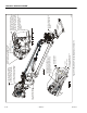
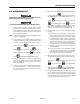
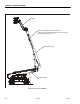
4.28 HOSE ROUTING PROCEDURE
For proper hose routing and cable wrap placement and
clamping, refer to Figure 4-29., Figure 4-30., Figure 4-31., Fig-
ure 4-50., Figure 4-51., and Figure 4-52. It is important to peri-
odically inspect hoses, wraps and clamps for proper slack
adjustments and clamping integrity (pull check). Any
changes as a result of inspection should be verified by per-
forming full strokes of boom functions especially lift, tele-
scope, jib, and platform rotate.
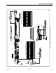
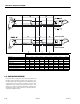
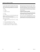
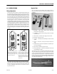
Switch States / Boom Length Regions
Dual Cap. Switch #1 Off Cam Off Cam Off Cam Disagree On Cam On Cam On Cam Disagree Disagree
Dual Cap. Switch #2 On Cam On Cam On Cam Disagree Off Cam Off Cam Off Cam Disagree Disagree
Control System Conclusion of Dual Cap. Switches B/A B/A B/A Disagree C/D C/D C/D Disagree Disagree
Main Transport Switch #1 Off Cam Disagree On Cam On Cam On Cam Disagree Off Cam Off Cam Disagree
Main Transport Switch #2 On Cam Disagree Off Cam Off Cam Off Cam Disagree On Cam On Cam Disagree
Control System Conclusion of Main Transport Switches A/D Disagree B/C B/C B/C Disagree A/D A/D Disagree
Control System Conclusion of Main Boom Length A A/B B B/C C C/D D Switch Fault Switch Fault
Table 4-2. Boom Switch Logic