
Service Manual Instruction Manual

SECTION 4 - BOOM & PLATFORM
3121171 – JLG Lift – 4-79
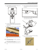
16. If the main boom angle sensors are calibrated and oper-
ating properly, the control system will now allow main
lift up/down below main boom angles of +65°.
17. Activate main lift and elevate the boom enough to gain
access to remove the main lift cylinder.
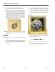
18. Use a crane or other suitable supporting device to sup-
port the weight of the main boom assembly.
NOTE: The main boom assembly weighs approximately 6500 lbs.
(2950 kg).
19. Put a nylon strap capable of supporting the weight of
the lift cylinder around the cylinder.
NOTE: The main lift cylinder weighs approximately 785 lbs. (356
kg).
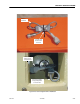
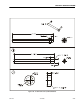
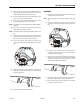
20. At the barrel end of the cylinder, place blocking under
the lower link and between the upper and lower links so
they do not drop when the pivot pin is removed.
21. Remove the retaining bolt, keeper pin, and pivot pin
securing the barrel end of the lift cylinder to the lower
link.
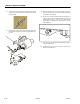
22. At the rod end of the cylinder, remove the retaining bolt,
keeper pin, and pivot pin securing the rod end of the lift
cylinder to the boom.
23. Remove the cylinder from the machine.
Installation
1. Using an adequate lifting device, position the main lift
cylinder in place on the machine.
NOTE: The main lift cylinder weighs approximately 785 lbs. (356
kg).
2. Install the retaining bolt, keeper pin, and pivot pin
securing the barrel end of the lift cylinder to the lower
link.
3. If necessary, refer to Removal and use the analyzer Ser-
vice Mode to cycle the cylinder in and out several times
to purge air from the cylinder.
4. At the rod end of the cylinder, install the retaining bolt,
keeper pin, and pivot pin securing the rod end of the lift
cylinder to the boom. It may be necessary to use the
analyzer Service Mode to align the pin.
5. Remove the blocking placed under the lower link and
between the upper and lower links during removal.
6. Refer to Removal, and use the analyzer Service Mode
procedure to lower the boom.