
Service Manual Instruction Manual

SECTION 4 - BOOM & PLATFORM
4-74 – JLG Lift – 3121171
5. Secure the pin in place with the retaining pin and retain-
ing pin bolt on the other end. Torque the bolt to 285
ft.lbs. (386 Nm).
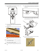
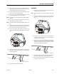
6. Install the sensor pin, sensor arm, and angle sensor. Con-
nect the wiring harness to the sensor and install the sen-
sor cover.
7. Cycle the cylinder in and out several times to purge air
from the cylinder. If necessary, refer to Removal and use
the analyzer Service Mode.
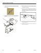
8. At the rod end of the cylinder, install the retaining bolt
and pivot pin that secures that end of the cylinder to the
tower boom. It may be necessary to use the analyzer
Service Mode to align the pin. Torque the bolt to 285
ft.lbs. (386 Nm).
9. If necessary, use the analyzer Service Mode procedure to
lower the tower boom.
10. Re-calibrate the boom sensors. Refer to Section 6.17,
Boom Sensor Calibration.