
Service Manual Instruction Manual

SECTION 4 - BOOM & PLATFORM
4-72 – JLG Lift – 3121171
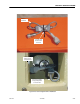
25. Disconnect the wiring harness from the strain relief con-
nector at the opposite side of the load sensing pin.
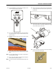
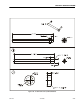
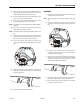
26. Use the Load Pin Removal Tool (JLG P/N 4846765) to pre-
vent the pin from being damaged, and use a hammer to
remove the pin. To make the tool refer to Figure 4-49.,
Load Pin Removal Tool, JLG P/N 4846765. If the Load Pin
Removal Tool is not available, use an arbor of the proper
size (as shown below). If excessive force is necessary to
move the pin, it may be necessary to carefully activate
lift using the auxiliary power switch to relieve lift cylin-
der weight from the load sensing pin.
27. After both retaining pins have been removed, carefully
remove the lift cylinder, repositioning the lifting strap as
necessary.
Installation
NOTE: The tower lift cylinder weighs approximately 644 lbs. (292
kg).
1. Put a nylon strap capable of supporting the weight of
the lift cylinder around the cylinder. Carefully position
the lift cylinder in place, repositioning the lifting strap as
necessary.
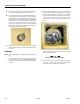
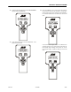
2. When installing a new load sensing pin, make sure all of
the holes in the turntable and lift cylinder are aligned. If
the new load sensing pin does not push 1/2 to 3/4 of the
way in by hand, remove the pin and align the holes bet-
ter. Also make sure the pin is installed with the strain
relief connector opposing the pin orientation bar as
shown.
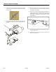
3. Using a wooden block, carefully tap the pin until it is
fully installed. Secure the pin in place with the retaining
pin and retaining pin bolt.
DO NOT TAP ON THE CENTER OF THE PIVOT PIN.
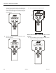
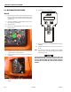
4. Connect the wiring harness to the strain relief connector
as shown in Figure 4-48., Load Sensing Pin Harness
Installation and re-calibrate the boom sensors.