
Service Manual Instruction Manual

SECTION 4 - BOOM & PLATFORM
4-54 – JLG Lift – 3121171
4.19 MAIN BOOM TRANSPORT ANGLE SWITCH
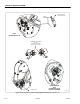
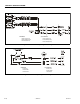
See Figure 4-35., Boom Sensor Locations - Dual Capacity, Length,
& Main Boom Transport and Figure 4-42., Main Boom Transport
Angle Switch Wiring
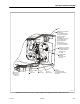
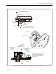
The Main Boom Transport Angle Switch is located on the left
side of the tower fly boom underneath the cover. This switch is
used as a backup for the rotary angle sensors and trips (acti-
vates) when the main boom is approximately 15° above the
tower boom. It is used to find the transport position in the
event of a rotary angle sensor failure and also used during
Electrical Retrieval (see Section 4.9, Electrical Retrieval System)
to assist in determining the angle of the main boom when a
fault is detected to any sensor in the Envelope Control System
(see Section 4.6, Envelope Control System).
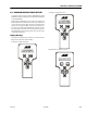
While conducting boom sensor calibration (see Section 6.17,
Boom Sensor Calibration), “position 2” states to lift up the
main boom to stop. The control system will stop the main
boom lift up function at the main boom angle limit switch trip
point (approx 15°).
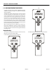
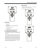
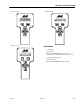
Analyzer Readings
The analyzer reading for these switches can be found in the
Diagnostics menu under Transport Data.
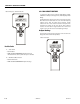
In the Transport position, the screen should read:
and
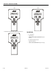
In the OUT of transport position, the screen should read