
Service Manual Instruction Manual

SECTION 4 - BOOM & PLATFORM
4-12 – JLG Lift – 3121171
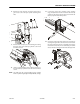
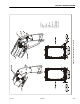
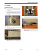
13. If necessary, remove the shoulder screws, retaining ring,
and pin that secures the barrel end of the level cylinder
to the main boom fly section and remove the level cylin-
der from the fly section.
Assembly
1. If removed during assembly, install the level cylinder
into the fly section. Install the shoulder screws, retaining
ring, and pin that secures the barrel end of the level cyl-
inder to the main boom fly section.
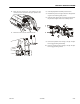
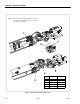
2. If removed during assembly, install the pin retainer
sleeve, bolt (screw prior to S/N 80869), and nut securing
the lower link to the upper link. On machines using the
bolt and nut, torque to 190 ft. lbs. (260 Nm). Position the
upper link to the boom nose and secure in place with
the pivot pin, keeper pin, and bolt.
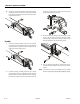
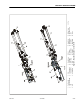
3. If removed during assembly, install the telescope cylin-
der into the fly section. Install the shoulder screws,
retaining rings, and pin that secures the rod end of the
telescope cylinder to the main boom fly section.
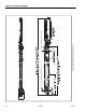
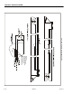
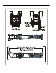
4. Using an adequate lifting device, slide the main fly sec-
tion and telescope cylinder into the main boom base
section.
NOTE: The main boom fly section including telescope cylinder
and level cylinder weighs approximately 2000 lbs. (907 kg)
.