
Service Manual Instruction Manual

SECTION 4 - BOOM & PLATFORM
3121171 – JLG Lift – 4-9
duction of slow down by flashing the creep light on the plat-
form display panel. This feature applies to both platform and
ground controls, however, no indication is made on the
ground control panel.
NOTE: For more detailed information concerning system adjust-
ment and operation, refer to Section 6 - JLG Control Sys-
tem.
4.13 DUAL CAPACITY SYSTEM
The Dual Capacity System is a multiple envelope control sys-
tem as opposed to a capacity indication system. The control
system changes the allowable working envelope to match the
capacity select mode to either the 500# (230 kg) mode or the
1000# (450 kg) mode. It then displays the capacity mode on
the platform and ground display panel and controls the posi-
tions of the main boom within the allowable envelope for that
mode. This mode is selectable by the operator with the dual
capacity select switch on the platform control panel.
The 500# (230 kg) mode has the largest envelope and allows
the use of the side swing jib. The 1000# (450 kg) mode has a
smaller envelope and requires the jib to be fixed in the cen-
tered position.
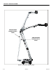
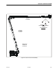
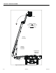
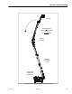
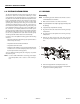
The control system uses the envelope control sensors (item16)
in addition to the 4 limit switches and cams mounted on the
main base and fly booms to restrict the main boom length
between the main boom angles of +55° and –45° for the 1000#
envelope.
To select the 1000# (450 kg) mode the boom must already be
in the smaller 1000# (450 kg) envelope and the jib must be
centered (+/-10 degrees) verified to the control system by the
jib centered limit switch mounted on the side swing rotator.
When the operator selects the 1000# (450 kg) mode and these
conditions are met, the capacity light changes from 500# (230
kg) to 1000# (450 kg), jib swing is disallowed, and the enve-
lope is changed accordingly.
When the operator selects the 1000# mode and these condi-
tions are not met, both capacity lights will flash, the platform
alarm will sound, and all functions except jib swing will be dis-
abled until the capacity select switch is put back into the 500#
(230 kg) position. Operation of jib swing in this condition can
be used to find the center position of the jib as the jib swing
function will stop when the center position is reached.
When in the 1000# (450 kg) mode, attempts to telescope, lift
or lower the main boom into the restricted area will cause that
function to be prevented.
NOTE: For more detailed information concerning system adjust-
ment and operation, refer to Section 6 - JLG Control Sys-
tem.
4.14 HYDRAULIC SYSTEM WARM UP
For optimal life and performance of the hydraulic system in
extremely cold temperatures, the control system monitors the
hydraulic system temperature and automatically limits the
function speeds of the high demand functions.
While the system is cold and in the warm up mode, the tower
lift, main lift, and main telescope functions are limited to creep
speeds and is indicated to the operator by flashing the creep
light on the platform control panel.
Operating the machine while in the warm up mode will gener-
ate sufficient heat to bring the hydraulic temperature up to
allowable temperatures and the warm up mode will be auto-
matically turned off. Although operating any function will
generate heat, the tower lift function will warm the hydraulic
system temperature the fastest as this function will operate
tower lift, tower telescope, and main lift function automati-
cally.
Functions being operated when the warm up mode turns off
will remain in the creep speed until the function is re-initiated.
NOTE: For more detailed information concerning system adjust-
ment and operation, refer to Section 6 - JLG Control Sys-
tem.
4.15 REDUCED PLATFORM HEIGHTS
The control system allows the maximum platform height of
the machine to be restricted to a selectable reduced height to
allow increased versatility in the rental market. The selection
of 125, 100, and 80 ft maximum platform heights are available
in the dealer mode - machine set up menu on the analyzer.
The reduced platform heights are implemented by restricting
the travel of the tower boom up the tower path (see Section
4.7, Tower Path Control System) while maintaining all other
aspects of the envelope control system (see Section 4.6, Enve-
lope Control System). The limits and functionality of the main
boom are unaffected by the selection.