
Service Manual Instruction Manual

SECTION 4 - BOOM & PLATFORM
4-8 – JLG Lift – 3121171
4.9 ELECTRICAL RETRIEVAL SYSTEM
The Electrical Retrieval System provides a backup means of
retrieving an elevated boom in the event of a failure of any
sensor used in the envelope control system (see Section 4.6,
Envelope Control System). Although the system is continu-
ously monitored for its viability, it is not
active until a failure of
the envelope control system is detected.
The system uses a load cell pin to attach the tower lift cylinder
to the turntable. This pin is instrumented with gauges allow-
ing the forces in the pin to be monitored. The control system
uses these force readings to select one of two sequences of
retrieving the boom in a manner necessary to maintain the
stability and structural integrity of the machine.
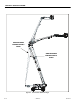
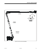
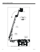
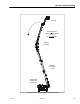
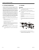
The two sequences of boom retrieval are determined based
on the boom being closest to a position of forward stability
concern or closest to a position of backward stability concern
(See Figure 4-2., Figure 4-3., and Figure 4-4.). Regardless of the
sequence selected by the control system, the control system
must recognize successive positions of the main and tower
booms before continuing with the sequence.
While operating in this mode, the positions of the booms are
determined by sensors not used by the primary envelope con-
trol system. These include the tower length switch, tower cyl-
inder angle sensor, main boom angle switch, and main boom
length switches.
Operating in this mode will result in reduced function speeds,
BCS warning light illumination, and restriction of functions.
Attempts to operate restricted functions will flash the BCS
light and sound the platform alarm.
NOTE: For more detailed information concerning system adjust-
ment and operation, refer to Section 6 - JLG Control Sys-
tem.
4.10 HYDRAULIC RETRIEVAL SYSTEM
The Hydraulic Retrieval System provides a backup means of
retrieving an elevated boom in the event of a recognized fail-
ure within the primary hydraulic control system related to the
main lift, tower lift, and tower telescope functions. The control
system monitors the primary hydraulic control system for
short and open circuits, unexpected boom sensor response to
command, control valve spool position faults, internal valve
control module faults, and CAN BUS communication faults.
When a fault is detected, the control system automatically
bypasses the appropriate hydraulic components and using
alternative valves and control logic allows the operator to
return the boom to the ground. In some cases the boom will
be allowed to move only to the extent gravity is capable of
assisting and in other cases the boom will be powered to allow
complete retrieval to the transport position.
Although the envelope control system (see Section 4.6, Enve-
lope Control System) remains active during the hydraulic
retrieval, the tower lift functionality will follow the tower path
(see Section 4.7, Tower Path Control System) in an approxi-
mated fashion. Rather than the normal combined movements
of tower lift, tower telescope, and main lift, the tower lift
movements will move in an alternating sequence between
tower lift and tower telescope with the automatic main lift sys-
tem (see Section 4.8, Automatic Main Boom Control System)
disabled.
Operating in this mode will result in reduced function speeds,
and restriction of functions. Attempts to operate restricted
functions will flash the BCS light and sound the platform
alarm.
NOTE: For more detailed information concerning system adjust-
ment and operation, refer to Section 6 - JLG Control Sys-
tem.
4.11 CONTROLLED BOOM ANGLE SYSTEM
The Controlled Boom Angle System uses the envelope control
sensors to enhance the control of the boom by minimizing the
interaction of swing and drive functions with the envelope
edges. This interaction is due to two factors. First, the envelope
is controlled relative to gravity regardless of ground slope and
second, the turntable/boom mounting is effected by swing
and drive functions when the ground slope varies. This can
cause the boom position to vary within the envelope or even
violate the envelope edges when swinging or driving without
intentionally moving the boom. The controlled boom angle
system minimizes this effect by automatically introducing
either the tower or main boom lift up or down during swing
and drive commands to maintain a constant boom angle rela-
tive to gravity.
When the tower is below the tower transport angle and the
main boom is 25 degrees above the tower boom, the angle of
the main boom is controlled. When the tower is above the
tower transport angle, the angle of the tower is controlled
regardless of main boom position.
Just as the booms are controlled during swing and drive func-
tions, the tower angle is also controlled during main boom lift
and main boom telescope functions.
Controlled boom angle is disabled with any envelope violation
or failure.
NOTE: For more detailed information concerning system adjust-
ment and operation, refer to Section 6 - JLG Control Sys-
tem.
4.12 SLOW DOWN SYSTEM
To reduce the machine dynamics and improve operator con-
trol, the control system uses the envelope control sensors to
automatically slow down the tower lift up, main lift up, and
main lift down function speeds as the minimum and maxi-
mum angles of the working envelope are approached. The
control system indicates to the operator this automatic intro-