
Service Manual Instruction Manual

SECTION 4 - BOOM & PLATFORM
3121171 – JLG Lift – 4-1
SECTION 4. BOOM & PLATFORM
4.1 PLATFORM CONTROL ENABLE SYSTEM
The platform controls make use of a time dependent enable
circuit to limit the time availability of "live" or enabled controls.
To operate any directional function, the footswitch must be
depressed before activation of the function. When the foot-
switch is depressed, the controls are enabled and the operator
has 7 seconds to operate any function. The controls will
remain enabled as long as the operator continues to use any
function and will remain enabled 7 seconds after the last func-
tion has been used. While the controls are "live", the enable
light will be illuminated in the platform display panel. When
the time limit has been reached, the enable light will turn off
and the controls will be "dead" or disabled. To continue use of
the machine the controls must be re-enabled to start the timer
system over again. This is done by releasing all functions, then
releasing and re-depressing the footswitch.
NOTE: For more detailed information concerning system adjust-
ment and operation, refer to Section 6 - JLG Control Sys-
tem.
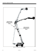
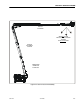
4.2 TRANSPORT POSITION SENSING SYSTEM
The Transport Position Sensing System uses the following sen-
sors to sense when the boom is in the position associated with
high speed travel.
• Main boom angle sensors (mounted at the tower to main
boom pivot pin)
• The main boom angle limit switch will be used in the event
of a main boom angle sensor fault
• Four main boom length limit switches (mounted on the
main base boom)
• Tower lift cylinder angle sensor (mounted at the tower lift
cylinder pivot to the turntable)
• The tower angle sensors in conjunction with the chassis tilt
sensor will be used in the event of a tower lift cylinder
angle sensor fault
• Tower boom length sensors (mounted in the pivot end of
the tower base boom)
• The tower length switch will be used in the event of a
tower length sensor fault.
• The position of the articulated jib is not considered
This system is used in the control of the following systems:
• Beyond Transport - Drive Speed Cutback System
• Drive/Steer - Boom Function Interlock System - CE Only
•Jib Stow System
• Electrical Retrieval System
• Swing Speed Proportioning System
• Axle Extension System
• Oscillating Axle System
NOTE: For more detailed information concerning system adjust-
ment and operation, refer to Section 6 - JLG Control Sys-
tem.
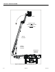
4.3 BEYOND TRANSPORT - DRIVE SPEED CUTBACK
SYSTEM
When boom is positioned beyond the transport position as
described in Section 4.2, Transport Position Sensing System,
the drive motors are automatically restricted to their maxi-
mum displacement position (slow speed). See Section 3.22,
Chassis Tilt Indicator System for interaction with the tilt sensor.
NOTE: For more detailed information concerning system adjust-
ment and operation, refer to Section 6 - JLG Control Sys-
tem.
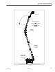
4.4 DRIVE/STEER – BOOM FUNCTION INTERLOCK
SYSTEM (CE ONLY)
The Drive/Steer – Boom Function Interlock System uses the
Transport Position Sensing System to sense when the boom is
out of the transport position. All controls are simultaneously
functional when the booms are within the transport position
as on the standard machine. When the boom is beyond the
transport position, the control functions are interlocked to
prevent simultaneous operation of any boom function with
drive/steer. The first function set to be operated while in this
mode, becomes the master function set. In other words, while
operating drive/steer functions the boom functions are inop-
erable. Likewise, while operating boom functions drive/steer
functions are inoperable.
NOTE: For more detailed information concerning system adjust-
ment and operation, refer to Section 6 - JLG Control Sys-
tem.