
Service Manual Instruction Manual

SECTION 3 - CHASSIS & TURNTABLE
3-122 – JLG Lift – 3121171
The EMR2 is equipped with safety devices and measures in the
hardware and software in order to ensure emergency running
(Limp home) functions.
In order to switch the engine off, the EMR2 is switched in a de-
energized fashion over the ignition switch. A strong spring in
the actuator presses the control rod in the de-energized con-
dition into the zero position. As a redundancy measure, an
additional solenoid serves for switching off and this, indepen-
dently of the actuator, also moves the control rod in the de-
energized condition into the zero position.
After the programming, that is carried out over the ISO9141
interface, the EMR2 is possesses a motor-specific data set and
this is then fixedly assigned to the engine. Included in this are
the various application cases as well as the customer’s wishes
regarding a particular scope of function.
Each EMR2 module is matched by serial number to the engine.
Modules cannot be swapped between engines.
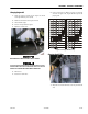
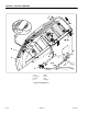
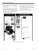
Figure 3-65. EMR 2 Engine Side Equipment
GLOW PLUG
POWER SUPPLY
COOLANT TEMPERATURE
SENSOR
CONTROL ROD POSITION
SENSOR/ACTUATOR
FLYWHEEL SPEED
SENSOR
OIL PRESSURE
SENSOR
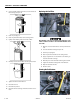
J LG S YS TE M U S ES JLG AN ALYZ ER TO RE PO RT FA ULT S
DIAGNOSIS INTERFACE/CAN-BUS; JLG SYSTEM USES THIS
TO CONTROL THE ENGINE & FAULT REPORTING.
JLG SYSTEM HANDLES ENGINE START/STOP; EMR2
TAKES CONTROL OF THE ENGINE AT 700RPM