
Service Manual Instruction Manual

SECTION 3 - CHASSIS & TURNTABLE
3121171 – JLG Lift – 3-101
Wear Tolerance
NOTE: In order to ensure the most accurate measurement, place
the indictor as close to the swing bearing as possible.
NOTE: As distances increase from the bearing the potential for
inaccuracies and unwarranted bearing replacement
increases. If access to an area close to the bearing is not
possible the indicator may be installed on the same plane
as the bearing.
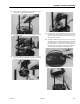
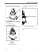
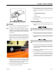
1. From the underside of the machine, at rear center, with
the main boom fully elevated and fully retracted, as
shown in Figure 3-52., Swing Bearing Tolerance Boom
Placement - Sheet 1 of 2, set up a magnetic base dial
indicator as shown below and set the indicator to 0
(zero).
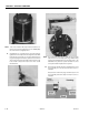
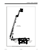
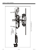
2. Next, position the main boom at horizontal and fully
extended, and the tower boom fully elevated and fully
extended as shown in Figure 3-53., Swing Bearing Toler-
ance Boom Placement - Sheet 2 of 2. Read the measure-
ment recorded on the dial indicator gauge.
3. If the measurement is greater than 0.094 in. (2.387 mm),
the swing bearing should be replaced.
4. If the measurement is less than 0.094 in. (2.387 mm), and
any of the following conditions exist, the bearing should
be removed, disassembled, and inspected for the fol-
lowing:
a. Metal particles in the grease.
b. Increased drive power required.
c. Noise.
d. Rough rotation.
5. If bearing inspection shows no defects, reassemble and
return to service.
Swing Bearing Removal
1. From Ground Control station, operate the boom ade-
quately to provide access to frame opening to rotary
coupling.
NEVER WORK BENEATH THE BOOM WITHOUT FIRST ENGAGING BOOM SAFETY
PROP OR PROVIDING ADEQUATE OVERHEAD SLING SUPPORT AND/OR BLOCK-
ING.
2. Attach an adequate support sling to the boom and draw
all slack from sling. Prop or block the boom if feasible.
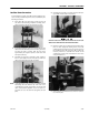
3. From inside turntable, remove mounting hardware
which attach rotary coupling retaining yoke brackets to
turntable.
HYDRAULIC LINES AND PORTS SHOULD BE CAPPED IMMEDIATELY AFTER DIS-
CONNECTING LINES TO AVOID THE ENTRY OF CONTAMINANTS INTO THE SYS-
TEM.
4. Tag and disconnect the hydraulic lines from the fittings
on the top of the rotary coupling. Use a suitable con-
tainer to retain any residual hydraulic fluid. Immediately
cap lines and ports.
5. Attach suitable overhead lifting equipment to the base
of the turntable weldment.
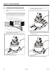
6. Use a suitable tool to scribe a line on the inner race of
the swing bearing and on the underside of the turnta-
ble. This will aid in aligning the bearing upon installa-
tion. Remove the bolts and washers which attach the
turntable to the bearing inner race. Discard the bolts.
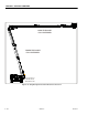
Figure 3-54. Swing Bolt Feeler Gauge Check