
Service Manual Instruction Manual

SECTION 3 - CHASSIS & TURNTABLE
3-80 – JLG Lift – 3121171
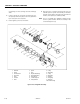
ing (8) taking care not to damage seals and carefully lay
aside.
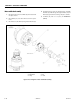
6. Loctite 2-off pins (19) in housing (2) followed by pres-
sure plate (4) and friction plates i.e. an inner (3) followed
by an outer (6) in correct sequence.
7. Position gasket (7) in correct orientation.
8. Align two holes in cylinder with dowel pins (19) and
assemble piston & cylinder sub-assembly to remainder
of brake securing with 6-off socket head capscrews and
washers (13 & 14). Torque to 55ft/lbs. (75 Nm).
NOTE: The use of a suitable press (hydraulic or arbor) Pressing
down on cylinder end face “B” will ease assembly of the
socket head capscrews (13).
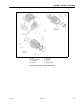
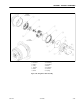
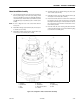
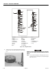
1. Brake Shaft
2. Housing
3. Inner Friction Plate
4. Pressure Plate
5. Gasket
6. Outer Plate
7. Gasket
8. Cylinder
9. Piston
10. Deep Groove Ball Bearing
11. Internal Retaining Ring
12. Rotary Shaft Seal
13. Socket Head Capscrew
14. Shakeproof Washer
15. O-Ring
16. Backing Ring
17. O-Ring
18. Backing Ring
19. Dowel Pin
20. Hexagon Plug
21. Plastic Plug
21A.Socket Pressure Plug
Figure 3-48. Swing Brake Assembly