Operation and Safety Manual Original Instructions - Keep this manual with the machine at all times.
FOREWORD FOREWORD This manual is a very important tool! Keep it with the machine at all times. The purpose of this manual is to provide owners, users, operators, lessors, and lessees with the precautions and operating procedures essential for the safe and proper machine operation for its intended purpose. Due to continuous product improvements, JLG Industries, Inc. reserves the right to make specification changes without prior notification. Contact JLG Industries, Inc. for updated information.
FOREWORD SAFETY ALERT SYMBOLS AND SAFETY SIGNAL WORDS This is the Safety Alert Symbol. It is used to alert you to the potential personal injury hazards. Obey all safety messages that follow this symbol to avoid possible injury or death INDICATES AN IMMINENTLY HAZARDOUS SITUATION. IF NOT AVOIDED, WILL RESULT IN SERIOUS INJURY OR DEATH. THIS DECAL WILL HAVE A RED BACKGROUND. INDICATES A POTENTIALLY HAZARDOUS SITUATION. IF NOT AVOIDED, MAY RESULT IN MINOR OR MODERATE INJURY.
FOREWORD For: THIS PRODUCT MUST COMPLY WITH ALL SAFETY RELATED BULLETINS. CONTACT JLG INDUSTRIES, INC. OR THE LOCAL AUTHORIZED JLG REPRESENTATIVE FOR INFORMATION REGARDING SAFETY-RELATED BULLETINS WHICH MAY HAVE BEEN ISSUED FOR THIS PRODUCT. • Accident Reporting • Product Safety Publications • Current Owner Updates JLG INDUSTRIES, INC. SENDS SAFETY RELATED BULLETINS TO THE OWNER OF RECORD OF THIS MACHINE. CONTACT JLG INDUSTRIES, INC. TO ENSURE THAT THE CURRENT OWNER RECORDS ARE UPDATED AND ACCURATE.
FOREWORD REVISION LOG d Original Issue - March 1, 2004 Revised - May 4, 2005 Revised - January 12, 2006 Revised - May 9, 2006 Revised - July 21, 2006 Revised - November 30, 2006 Revised - April 10, 2007 Revised - March 19, 2008 Revised - November 19, 2009 Revised - August 31, 2010 Revised - August 18, 2011 Revised - August 9, 2012 Revised - September 11, 2014 – JLG Lift – 3121170
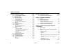
TABLE OF CONTENTS SECTION - PARAGRAPH, SUBJECT PAGE SECTION - PARAGRAPH, SUBJECT SECTION - 1 - SAFETY PRECAUTIONS 1.1 1.2 1.3 1.4 1.5 GENERAL . . . . . . . . . . . . . . . . . . . . . . . . . . . . . . . . . . . . . . . . . . . . 1-1 PRE-OPERATION . . . . . . . . . . . . . . . . . . . . . . . . . . . . . . . . . . . . . 1-1 Operator Training and Knowledge . . . . . . . . . . . . . . . . . 1-1 Workplace Inspection. . . . . . . . . . . . . . . . . . . . . . . . . . . . . . 1-2 Machine Inspection. . . .
TABLE OF CONTENTS SECTION - PARAGRAPH, SUBJECT 4.4 4.5 4.6 4.7 4.8 4.9 4.10 4.11 4.12 4.13 4.14 4.15 ii PAGE AUXILIARY POWER OPERATION . . . . . . . . . . . . . . . . . . . . . 4-10 CAPACITY SELECT. . . . . . . . . . . . . . . . . . . . . . . . . . . . . . . . . . . 4-10 ENGINE OPERATION . . . . . . . . . . . . . . . . . . . . . . . . . . . . . . . . 4-12 Starting Procedure . . . . . . . . . . . . . . . . . . . . . . . . . . . . . . . 4-12 Shutdown Procedure . . . . . . . . . . . . . . . . . . . . . .
TABLE OF CONTENTS SECTION - PARAGRAPH, SUBJECT 6.3 6.4 6.5 PAGE SECTION - PARAGRAPH, SUBJECT PAGE OPERATOR MAINTENANCE . . . . . . . . . . . . . . . . . . . . . . . . . . 6-17 TIRES & WHEELS. . . . . . . . . . . . . . . . . . . . . . . . . . . . . . . . . . . . . 6-33 Tire Inflation. . . . . . . . . . . . . . . . . . . . . . . . . . . . . . . . . . . . . 6-33 Tire Damage. . . . . . . . . . . . . . . . . . . . . . . . . . . . . . . . . . . . . 6-33 Tire Replacement . . . . . . . . . . . . . . . . . . .
TABLE OF CONTENTS SECTION - PARAGRAPH, SUBJECT PAGE SECTION - PARAGRAPH, SUBJECT PAGE This Page Left Blank Intentionally.
LIST OF FIGURES FIGURE NUMBER - TITLE 2-1. 2-2. 2-3. 3-1. 3-1. 3-2. 3-3. 4-1. 4-2. 4-3. 4-4. 4-5. 4-6. 4-7. 4-8. 4-9. 4-10. 4-11. 4-12. 4-13. 6-1. 6-2. 6-3. 3121170 PAGE FIGURE NUMBER - TITLE Basic Nomenclature. . . . . . . . . . . . . . . . . . . . . . . . . . . . . . . . . . 2-7 Daily Walk-Around Inspection - Sheet 1 of 2 . . . . . . . . . . 2-8 Daily Walk-Around Inspection - Sheet 2 of 2 . . . . . . . . . . 2-9 Ground Control Station . . . . . . . . . . . . . . . . . . . . . . . . . . . . . .
LIST OF FIGURES FIGURE NUMBER - TITLE PAGE FIGURE NUMBER - TITLE PAGE This Page Left Blank Intentionally.
LIST OF TABLES TABLE NUMBER - TITLE 1-1 1-2 2-1 4-1 4-2 6-1 6-2 6-3 6-4 6-5 6-6 6-7 6-8 6-9 6-10 6-11 6-12 6-13 6-14 6-15 6-16 6-17 6-18 6-19 7-1 3121170 PAGE TABLE NUMBER - TITLE PAGE Minimum Approach Distances (M.A.D.) . . . . . . . . . . . . . . . 1-6 Beaufort Scale (For Reference Only). . . . . . . . . . . . . . . . . . . 1-9 Inspection and Maintenance Table . . . . . . . . . . . . . . . . . . . 2-3 Decal Legend - Prior to S/N 0300141446 . . . . . . . . . . . . .
LIST OF TABLES TABLE NUMBER - TITLE PAGE TABLE NUMBER - TITLE PAGE This Page Left Blank Intentionally.
SECTION 1 - SAFETY PRECAUTIONS SECTION 1. SAFETY PRECAUTIONS 1.1 GENERAL This section outlines the necessary precautions for proper and safe machine usage and maintenance. It is mandatory that a daily routine is established based on the content of this manual to promote proper machine usage.
SECTION 1 - SAFETY PRECAUTIONS • An operator must not accept operating responsibilities until adequate training has been given by competent and authorized persons. • Allow only those authorized and qualified personnel to operate the machine who have demonstrated that they understand the safe and proper operation and maintenance of the unit. • Precautions to avoid all hazards in the work area must be taken by the user before and during operation of the machine.
SECTION 1 - SAFETY PRECAUTIONS Machine Inspection 1.3 • Do not operate this machine until the inspections and functional checks as specified in Section 2 of this manual have been performed. General • Do not operate this machine until it has been serviced and maintained according to the maintenance and inspection requirements as specified in the machine’s Service and Maintenance Manual. • Ensure all safety devices are operating properly. Modification of these devices is a safety violation.
SECTION 1 - SAFETY PRECAUTIONS • Do not carry materials directly on platform railing unless approved by JLG. • When two or more persons are in the platform, the operator shall be responsible for all machine operations. • Always ensure that power tools are properly stowed and never left hanging by their cord from the platform work area. Trip and Fall Hazards • During operation, occupants in the platform must wear a full body harness with a lanyard attached to an authorized lanyard anchorage point.
SECTION 1 - SAFETY PRECAUTIONS • Before operating the machine, make sure all gates are closed and fastened in their proper position. Electrocution Hazards • This machine is not insulated and does not provide protection from contact or proximity to electrical current. • Keep both feet firmly positioned on the platform floor at all times. Never position ladders, boxes, steps, planks, or similar items on unit to provide additional reach for any purpose.
SECTION 1 - SAFETY PRECAUTIONS Table 1-1. Minimum Approach Distances (M.A.D.) • Allow for machine movement and electrical line swaying.
SECTION 1 - SAFETY PRECAUTIONS • The minimum approach distance may be reduced if insulating barriers are installed to prevent contact, and the barriers are rated for the voltage of the line being guarded. These barriers shall not be part of (or attached to) the machine. The minimum approach distance shall be reduced to a distance within the designed working dimensions of the insulating barrier.
SECTION 1 - SAFETY PRECAUTIONS • Never exceed the maximum work load as specified on the platform. Keep all loads within the confines of the platform, unless authorized by JLG. • Do not operate the machine when wind conditions exceed 28 mph (12.5 m/s). Refer to Table 1-2, Beaufort Scale (For Reference Only). • Keep the chassis of the machine a minimum of 2 ft. (0.6m) from holes, bumps, drop-offs, obstructions, debris, concealed holes, and other potential hazards at the ground level.
SECTION 1 - SAFETY PRECAUTIONS DO NOT OPERATE THE MACHINE WHEN WIND CONDITIONS EXCEED 28 MPH (12.5 M/ S). Table 1-2. Beaufort Scale (For Reference Only) 3121170 Wind Speed Beaufort Number mph m/s 0 0 0-0.2 Calm Calm. Smoke rises vertically 1 1-3 0.3-1.5 Light air Wind motion visible in smoke 2 4-7 1.6-3.3 Light breeze Wind felt on exposed skin. Leaves rustle Description Land Conditions 3 8-12 3.4-5.4 Gentle breeze Leaves and smaller twigs in constant motion 4 13-18 5.5-7.
SECTION 1 - SAFETY PRECAUTIONS • Keep non-operating personnel at least 6 ft. (1.8m) away from machine during all driving and swing operations. Crushing and Collision Hazards • Approved head gear must be worn by all operating and ground personnel. • Check work area for clearances overhead, on sides, and bottom of platform when lifting or lowering platform, and driving.
SECTION 1 - SAFETY PRECAUTIONS 1.4 TOWING, LIFTING, AND HAULING 1.5 • Never allow personnel in platform while towing, lifting, or hauling. This sub-section contains general safety precautions which must be observed during maintenance of this machine. Additional precautions to be observed during machine maintenance are inserted at the appropriate points in this manual and in the Service and Maintenance Manual.
SECTION 1 - SAFETY PRECAUTIONS • DO NOT use your hand to check for leaks. Use a piece of cardboard or paper to search for leaks. Wear gloves to help protect hands from spraying fluid. • Do not use machine as a ground for welding. • When performing welding or metal cutting operations, precautions must be taken to protect the chassis from direct exposure to weld and metal cutting spatter. • Do not refuel the machine with the engine running. • Use only approved non-flammable cleaning solvents.
SECTION 1 - SAFETY PRECAUTIONS Battery Hazards • Always disconnect batteries when servicing electrical components or when performing welding on the machine. • Do not allow smoking, open flame, or sparks near battery during charging or servicing. BATTERY FLUID IS HIGHLY CORROSIVE. AVOID CONTACT WITH SKIN AND CLOTHING AT ALL TIMES. IMMEDIATELY RINSE ANY CONTACTED AREA WITH CLEAN WATER AND SEEK MEDICAL ATTENTION. • Do not contact tools or other metal objects across the battery terminals.
SECTION 1 - SAFETY PRECAUTIONS NOTES: 1-14 – JLG Lift – 3121170
SECTION 2 - USER RESPONSIBILITIES, MACHINE PREPARATION, AND INSPECTION SECTION 2. USER RESPONSIBILITIES, MACHINE PREPARATION, AND INSPECTION 6. The safest means to operate the machine where overhead obstructions, other moving equipment, and obstacles, depressions, holes, drop-offs. 2.1 PERSONNEL TRAINING The aerial platform is a personnel handling device; so it is necessary that it be operated and maintained only by trained personnel.
SECTION 2 - USER RESPONSIBILITIES, MACHINE PREPARATION, AND INSPECTION 2.2 PREPARATION, INSPECTION, AND MAINTENANCE The following table covers the periodic machine inspections and maintenance required by JLG Industries, Inc. Consult local regulations for further requirements for aerial work platforms.
SECTION 2 - USER RESPONSIBILITIES, MACHINE PREPARATION, AND INSPECTION Table 2-1. Inspection and Maintenance Table Type Primary Responsibility Frequency Service Qualification Reference Pre-Start Inspection Before using each day; or whenever there’s an Operator change. User or Operator User or Operator Operator and Safety Manual Pre-Delivery Inspection (See Note) Before each sale, lease, or rental delivery.
SECTION 2 - USER RESPONSIBILITIES, MACHINE PREPARATION, AND INSPECTION 4. Operation and Safety Manuals – Make sure a copy of the Operator and Safety Manual, AEM Safety Manual (ANSI markets only), and ANSI Manual of Responsibilities (ANSI markets only) is enclosed in the weather resistant storage container. Pre-Start Inspection The Pre-Start Inspection should include each of the following: 1. Cleanliness – Check all surfaces for leakage (oil, fuel, or battery fluid) or foreign objects.
SECTION 2 - USER RESPONSIBILITIES, MACHINE PREPARATION, AND INSPECTION 11. Function Check – Once the “Walk-Around” Inspection is complete, perform a functional check of all systems in an area free of overhead and ground level obstructions. Refer to Section 4 for more specific operating instructions. Function Check IF THE MACHINE DOES NOT OPERATE PROPERLY, TURN OFF THE MACHINE IMMEDIATELY! REPORT THE PROBLEM TO THE PROPER MAINTENANCE PERSONNEL.
SECTION 2 - USER RESPONSIBILITIES, MACHINE PREPARATION, AND INSPECTION 2. From the platform control console: a. Ensure that the control console is firmly secured in the proper location; c. Check that all boom functions are disabled with the axles retracted and the boom out of transport mode. NOTE: b. Check that all guards protecting the switches or locks are in place; c. Operate all functions and make sure the Boom Control System warning light does not come on; d.
SECTION 2 - USER RESPONSIBILITIES, MACHINE PREPARATION, AND INSPECTION 1. 2. 3. 4. 5. 6. 7. 8. 9. 10. 11. 12. 13. 14. 15. Front Drive\Steer Wheels Rear Drive\Steer Wheels Tower Lift Cylinder Ground Console Tower Base Boom Section Tower Mid Boom Section Tower Fly Boom Section Tower Boom Assembly Main Lift Cylinder Main Base Boom Section Main Boom Fly Section Main Boom Assembly Jib Platform Platform Console Figure 2-1.
SECTION 2 - USER RESPONSIBILITIES, MACHINE PREPARATION, AND INSPECTION Figure 2-2.
SECTION 2 - USER RESPONSIBILITIES, MACHINE PREPARATION, AND INSPECTION 4. Swing Drive - No evidence of damage. General Begin the "Walk-Around Inspection" at Item 1, as noted on the diagram. Continue checking each item in sequence for the conditions listed in the following checklist. 5. Wheel/Tire Assemblies - Properly secured, no missing lug nuts. Inspect for worn tread, cuts, tears or other discrepancies. Inspect wheels for damage and corrosion. 6. Drive Motor, Brake, and Hub - No evidence of leakage. 7.
SECTION 2 - USER RESPONSIBILITIES, MACHINE PREPARATION, AND INSPECTION 2.3 6. Have an assistant check to see that left front or right rear wheel remains elevated in position off of the ground. OSCILLATING AXLE LOCKOUT TEST (IF EQUIPPED) The front axles will oscillate when the boom is in the transport position. 7. Carefully return the boom to the transport position. When boom reaches the transport position, carefully activate Drive to release cylinders.
SECTION 3 - MACHINE CONTROLS AND INDICATORS SECTION 3. MACHINE CONTROLS AND INDICATORS 3.1 NOTE: GENERAL THE MANUFACTURER HAS NO DIRECT CONTROL OVER MACHINE APPLICATION AND OPERATION. THE USER AND OPERATOR ARE RESPONSIBLE FOR CONFORMING WITH GOOD SAFETY PRACTICES. This section provides the necessary information needed to understand control functions. 3.2 CONTROLS AND INDICATORS NOTE: 3121170 All machines are equipped with control panels that use symbols to indicate control functions.
SECTION 3 - MACHINE CONTROLS AND INDICATORS 3. Tower Lift Control Provides raising and lowering of the tower boom. TO AVOID SERIOUS INJURY, DO NOT OPERATE MACHINE IF ANY CONTROL LEVERS OR TOGGLE SWITCHES CONTROLLING PLATFORM MOVEMENT DO NOT RETURN TO THE OFF POSITION WHEN RELEASED. 4. Swing Control Provides 360 degrees continuous turntable rotation. Ground Control Station 5. Main Lift Control (See Figure 3-1., Ground Control Station) Provides raising and lowering of the main boom. 1.
SECTION 3 - MACHINE CONTROLS AND INDICATORS 9 1 8 2 7 6 13 3 1. 2. 3. 4. 5. 6. 7. 8. 9. 10. 11. 12. 13. Indicator Panel Main Boom Telescope Tower Boom Lift Swing Main Boom Lift Jib Lift Platform Leveling Override Platform Rotate Jib Swing Platform/Ground Select Switch Hourmeter Power/Emergency Stop Engine Start/Auxiliary Power/Function Enable 12 11 4 5 10 Figure 3-1.
SECTION 3 - MACHINE CONTROLS AND INDICATORS 8. Platform Rotate 11. Hourmeter Allows rotation of the platform. Registers the amount of time the machine has been in use, with engine running. By connecting into the oil pressure circuit of the engine, only engine run hours are recorded. The hourmeter registers up to 9,999.9 hours and cannot be reset. 9. Jib Swing Allows swinging of the jib.
SECTION 3 - MACHINE CONTROLS AND INDICATORS NOTE: Auxiliary power only works if there is no engine oil pressure, and is disabled if engine is running. Ground Control Indicator Panel Functions will operate at a slower than normal rate because of the reduced hydraulic flow. WHEN USING AUXILIARY POWER, DO NOT OPERATE MORE THAN ONE FUNCTION AT A TIME. (SIMULTANEOUS OPERATION CAN OVERLOAD THE AUXILIARY PUMP. 13.
SECTION 3 - MACHINE CONTROLS AND INDICATORS 1. 2. 3. 3-6 Battery Charging 4. High Engine Oil Temp. 7. Platform Capacity Low Engine Oil Pressure 5. Glow Plug Indicator 8. Platform Overload High Engine Coolant Temp. 6. Axles Set 9. Boom Control System Warning Figure 3-1.
SECTION 3 - MACHINE CONTROLS AND INDICATORS 6. Axles Set Indicator Platform Station Indicates that the axles are fully extended. The indicator will flash as the axles are extending or retracting and be on solid when fully extended. The light will go out when the axles are fully retracted. 7. Platform Capacity Indicator Indicates which capacity range is selected. This capacity can only be selected at the platform control console. (See Figure 3-2.
SECTION 3 - MACHINE CONTROLS AND INDICATORS 1. 2. 3. 4. 5. 6. Power/Emergency Stop Engine Start / Aux Power Capacity Select Drive Orientation Override Drive/Steer Main Boom Telescope 7. 8. 9. 10. 11. 12. Lights Jib Lift Soft Touch Override Jib Swing Tower Boom Lift Soft Touch Indicator 13. 14. 15. 16. 17. 18. Platform Rotate Jib Stow Override Function Speed Control Main Lift / Swing Drive Speed / Torque Select Steer Select 19. 20. 21. 22.
SECTION 3 - MACHINE CONTROLS AND INDICATORS 2. Start/Auxiliary Power 4. Drive Orientation Override When pushed forward, the switch energizes the starter motor to start the engine. When the boom is swung over the rear tires or further in either direction, the Drive Orientation indicator will illuminate when the drive function is selected. Push and release the switch, and within 3 seconds move the Drive/Steer control to activate drive or steer.
SECTION 3 - MACHINE CONTROLS AND INDICATORS 6. Main Telescope NOTE: Allows extension and retraction of the main boom. 7. Lights (If Equipped) The Jib Swing function is not operable when the Capacity Select control is in the 1000 lb. (454 kg for ANSI markets and 450 kg for CE and Australia markets) position. 10. Jib Swing Operates accessory light packages if the machine is so equipped. Allows the operator to swing the jib to the left or right. 11. Tower Boom Lift 8.
SECTION 3 - MACHINE CONTROLS AND INDICATORS 14. Jib Stow Override NOTE: Allows the operator to swing the jib to the right past the electronic stop to stow the jib beside the boom for transport. When boom is positioned above transport position or telescoped out and any of the following switches, DRIVE SPEED/TORQUE SELECT or FUNCTION SPEED, are positioned to HIGH, high function speeds are automatically cut out and the machine continues to operate at a lower speed. 15.
SECTION 3 - MACHINE CONTROLS AND INDICATORS 18. Steer Select 20. Axle Extend/Retract The action of the steering system is operator selectable. The center switch position gives conventional front wheel steering with the rear wheels unaffected. This is for normal driving at maximum speeds. The forward position is for “crab” steering. When in this mode both front and rear axles steer in the same direction, which allows the chassis to move sideways as it goes forward.
SECTION 3 - MACHINE CONTROLS AND INDICATORS 4. Platform Capacity Indicator Platform Control Indicator Panel Indicates the maximum platform capacity selected for the platform. (See Figure 3-3., Platform Control Indicator Panel) 1. Level System Fault Indicator One of the capacity lights should be on at all times. Both lights will flash and an alarm will sound if the platform is out of the operating envelope for the selected capacity. Indicates a fault in the electronic leveling system.
SECTION 3 - MACHINE CONTROLS AND INDICATORS 1. 2. 3. 4. 5. 3-14 Level System 6. Glow Plug 11. Drive Orientation 12. Axles Set AC Generator 7. Enable 13. Boom Control System Warning Platform Overload 8. Fuel Level Platform Capacity 9. Creep Speed Tilt Alarm Warning 10. System Distress Figure 3-3.
SECTION 3 - MACHINE CONTROLS AND INDICATORS 6. Glow Plug/Wait to Start Indicator NOTE: If the engine fails to start due to cold temperatures or excessive amounts of smoke are produced on startup, wait for the glow plug/wait to start indicator to go out before starting the engine. Releasing the footswitch removes power from all controls and applies the drive brakes. 8. Fuel Level Indicator Indicates the level of fuel in the fuel tank. Indicates the glow plugs are operating.
SECTION 3 - MACHINE CONTROLS AND INDICATORS 10. System Distress Indicator 13. Boom Control System Warning Indicator The light indicates that the JLG Control System has detected a malfunction and a Diagnostic Trouble Code has been set in the system memory. Refer to the Service Manual for instructions concerning the trouble codes and trouble code retrieval. The malfunction indicator light will illuminate for 2-3 seconds when the key is positioned to the on position to act as a self test.
SECTION 4 - MACHINE OPERATION SECTION 4. MACHINE OPERATION 4.1 DESCRIPTION This machine is a self-propelled hydraulic personnel lift equipped with a work platform on the end of an elevating and rotating boom. 3121170 – JLG Lift – The primary operator control station is in the platform. From this control station, the operator can drive and steer the machine in both forward and reverse directions. The operator can raise or lower the main or tower boom or swing the boom to the left or right.
SECTION 4 - MACHINE OPERATION 4.2 HYDRAULIC SYSTEM WARM UP 4.3 The control system monitors the hydraulic system in extremely cold temperatures and provides optimal performance by automatically limiting the function speeds of the high demand functions. The warm up mode automatically shuts off when system oil reaches allowable temperatures.
SECTION 4 - MACHINE OPERATION Envelope Control System The Envelope Control System is the primary means of controlling the working positions of the tower and main boom within the stability and structural requirements of the machine. The main boom must be controlled in maximum angle and minimum angle to avoid entering a position that could compromise backward stability and avoid main boom to tower boom interference.
SECTION 4 - MACHINE OPERATION Tower Path Control System The Tower Path Control System uses the envelope control sensors to enhance the control of the tower boom for increased user efficiency and is used as an integral part of the envelope control system. Both the ground and platform control panels use one function switch to control the tower.
SECTION 4 - MACHINE OPERATION TOWER LIFT UP - MAIN BOOM ABOVE 60° Automatic Main Boom Control System During tower lift up with the main boom already above 60°, the control system will delay automatic compensation of the main boom angle during tower lift until the main boom reaches approximately 60°. The control system will then control the main boom to 60° until the tower boom has reached its maximum height.
SECTION 4 - MACHINE OPERATION Controlled Angle Swing Speed Proportioning The Controlled Boom Angle System minimizes the interaction of swing and drive functions with the envelope edges. This interaction is due to two factors. First, the envelope is controlled relative to gravity regardless of ground slope and second, the turntable/ boom mounting is effected by swing and drive functions when the ground slope varies.
SECTION 4 - MACHINE OPERATION MAIN BOOM FULLY EXTENDED MACHINE WILL TIP OVER IN DIRECTION OF ARROWS IF OVERLOADED OR OPERATED ON AN OUT-OF-LEVEL SURFACE TOWER BOOM FULLY LOWERED TO FULLY RAISED TURNTABLE ROTATED 90 DEGREES FROM STOWED POSITION Figure 4-2.
4-8 – JLG Lift – TURNTABLE ROTATED 90 DEGREES FROM STOWED POSITION Figure 4-3. Position of Least Backward Stability - Sheet 1 of 2 TOWER BOOM FULLY LOWERED TO FULLY RAISED MAIN BOOM FULLY ELEVATED MACHINE WILL TIP OVER IN DIRECTION OF ARROW IF OVERLOADED OR OPERATED ON AN OUT-OF-LEVEL SURFACE JIB ELEVATED SECTION 4 - MACHINE OPERATION .
3121170 – JLG Lift – Figure 4-4.
SECTION 4 - MACHINE OPERATION 4.4 AUXILIARY POWER OPERATION 4.5 The Auxiliary Power System provides a means of moving the platform in the event of an engine malfunction. This system uses an electric motor/pump unit capable of operating all boom functions needed to allow the platform to be lowered to ground level. With auxiliary power activated, the control system will attempt to use the force of gravity to operate main lift down, tower lift down, and tower telescope in.
Figure 4-5.
SECTION 4 - MACHINE OPERATION 4.6 NOTE: 2. After engine has had sufficient time to warm up, shut engine off. ENGINE OPERATION Initial starting should always be performed from the Ground Control console. 3. Turn SELECT switch to PLATFORM. 4. From Platform, pull POWER/EMERGENCY STOP switch out, then push the ENGINE START switch until engine starts. Starting Procedure NOTE: IF ENGINE FAILS TO START PROMPTLY, DO NOT CRANK FOR AN EXTENDED TIME.
SECTION 4 - MACHINE OPERATION 4.7 TRAVELING (DRIVING) See Figure 4-6., Grade and Side Slopes NOTE: Refer to the Operating Specifications table for Gradeability and Sideslope ratings. All ratings for Gradeability and Sideslope are based upon the machine’s boom being in the stowed position, fully lowered, and retracted. Traveling is limited by two factors: 1. Gradeability, which is the percent of grade of the incline the machine can climb.
SECTION 4 - MACHINE OPERATION Figure 4-6.
SECTION 4 - MACHINE OPERATION Traveling Forward and Reverse 4.9 1. At Platform Controls, pull out Emergency Stop switch, start engine, and activate footswitch. NOTE: 2. Position Drive controller to FORWARD or REVERSE as desired. This machine is equipped with a Drive Orientation Indicator. The yellow light on the platform control console indicates that the boom is swung beyond the rear drive tires and the machine may Drive/Steer in the opposite direction from the movement of the controls.
SECTION 4 - MACHINE OPERATION Platform Rotation Swinging the Boom To rotate the platform to the left or right, use the Platform Rotate control switch to select the direction and hold until desired position is reached. 4.11 BOOM To swing boom, use Swing control to select Right or Left direction. WHEN SWINGING THE BOOM MAKE SURE THERE IS AMPLE ROOM FOR THE BOOM TO CLEAR SURROUNDING WALLS, PARTITIONS AND EQUIPMENT. DO NOT SWING OR RAISE BOOM OUT OF TRANSPORT MODE WHEN MACHINE IS OUT OF LEVEL.
SECTION 4 - MACHINE OPERATION Tower Lift NOTE: 4.13 EMERGENCY TOWING The control system automatically uses a combination of tower telescope and tower lift for the tower boom to follow a predescribed path. To raise or lower the tower boom, use the Tower Boom Lift control to select Up or Down movement. RUNAWAY VEHICLE/MACHINE HAZARD. MACHINE HAS NO TOWING BRAKES. TOWING VEHICLE MUST BE ABLE TO CONTROL MACHINE AT ALL TIMES. ON-HIGHWAY TOWING NOT PERMITTED.
SECTION 4 - MACHINE OPERATION 3. Reconnect the drive hubs by inverting the disconnect cap when towing is complete. 4.14 SHUT DOWN AND PARK To shut down and park the machine, the procedures are as follows: 1. Drive machine to a reasonably well protected area. 2. Ensure boom is lowered over rear drive axle. 3. Push in the Emergency Stop at Platform Controls. 4. Push in the Emergency Stop at Ground Controls. Position Platform/Ground Select switch to center OFF. 5.
SECTION 4 - MACHINE OPERATION 1. Place the boom in the stowed position with the turntable locked. 4.15 LIFTING AND TIE DOWN (See Figure 4-8.) 2. Remove all loose items from the machine. Lifting 1. The weight of the machine is stamped on the serial number plate. If the plate is missing or illegible, call JLG Industries or weigh the individual unit to find out the Gross Vehicle Weight. 3.
SECTION 4 - MACHINE OPERATION Figure 4-8.
SECTION 4 - MACHINE OPERATION Figure 4-9.
SECTION 4 - MACHINE OPERATION Figure 4-10.
SECTION 4 - MACHINE OPERATION Figure 4-11.
SECTION 4 - MACHINE OPERATION Figure 4-12.
SECTION 4 - MACHINE OPERATION Figure 4-13.
SECTION 4 - MACHINE OPERATION Table 4-1.
SECTION 4 - MACHINE OPERATION Table 4-1.
SECTION 4 - MACHINE OPERATION Table 4-1.
SECTION 4 - MACHINE OPERATION Table 4-1.
SECTION 4 - MACHINE OPERATION Table 4-2.
SECTION 4 - MACHINE OPERATION Table 4-2.
SECTION 4 - MACHINE OPERATION Table 4-2.
SECTION 4 - MACHINE OPERATION Table 4-2.
SECTION 4 - MACHINE OPERATION NOTES: 4-34 – JLG Lift – 3121170
SECTION 5 - EMERGENCY PROCEDURES SECTION 5. EMERGENCY PROCEDURES 5.1 GENERAL This section explains the steps to be taken in case of an emergency situation while operating. 5.2 INCIDENT NOTIFICATION JLG Industries, Inc. must be notified immediately of any incident involving a JLG product. Even if no injury or property damage is evident, the factory should be contacted by telephone and provided with all necessary details.
SECTION 5 - EMERGENCY PROCEDURES Platform or Boom Caught Overhead 5.4 If the platform or boom becomes jammed or snagged in overhead structures or equipment, rescue platform occupants prior to freeing the machine. 5-2 EMERGENCY TOWING PROCEDURES Towing this machine is prohibited, unless properly equipped. However, provisions for moving the machine have been incorporated. For specific procedures, refer to Section 4.
SECTION 6 - GENERAL SPECIFICATIONS & OPERATOR MAINTENANCE SECTION 6. GENERAL SPECIFICATIONS & OPERATOR MAINTENANCE 6.1 INTRODUCTION 6.2 This section of the manual provides additional necessary information to the operator for proper operation and maintenance of this machine.
SECTION 6 - GENERAL SPECIFICATIONS & OPERATOR MAINTENANCE Table 6-1. Operating Specifications - Prior to S/N 0300141446 Maximum Wind Speed 28 mph (12.5 m/s) Maximum Manual Force 400 N Electrical System Voltage 12 Volts Max Tire Load 23,700 lbs. (10750 kg) Maximum Platform Rotation ±90° Table 6-2. Operating Specifications - S/N 0300141446 to Present JibPLUS Length Horizontal Motion Vertical Motion Table 6-2.
SECTION 6 - GENERAL SPECIFICATIONS & OPERATOR MAINTENANCE Dimensional Data Chassis Table 6-3. Dimensional Data Overall Width Axles Retracted Axles Extended 8ft. 2in. (2.49 m) 12ft. 6in. (3.8 m) Stowed Height 10ft. (3.05 m) Stowed Length (Transport Mode) 37 ft. 7 in. (11.46 m) Stowed Length (Working Mode) 47 ft. 6 in. (14.48 m) Wheelbase 12ft. 6in. (3.81 m) Tailswing Tower Up Tower Down 7 ft. (2.13 m) 11 ft. 3 in. (3.43 m) Oscillating Axle ±6 in. (0.15 m) Ground Clearance (Axle) 12 in. (30.
SECTION 6 - GENERAL SPECIFICATIONS & OPERATOR MAINTENANCE Capacities Tires Table 6-6. Tire Specifications Table 6-5. Capacities Size 445/50D710 Hydraulic Tank 53.3 gallons (201.7 liters) Load Range J Fuel Tank 31 gallons (117 liters) Ply Rating 18 Hydraulic System 65.4 gallons (247.5 liters) Foam Fill Polyurethane HD (55 Durometer) Foam Diameter 46.45 in. (117.9 cm) Width 18 in. (45.7 cm) Rim Size 15x28 Tire & Wheel Weight 867 lbs.
SECTION 6 - GENERAL SPECIFICATIONS & OPERATOR MAINTENANCE Engine Data - Deutz 2011 Prior to S/N 0300127698 Engine Data - Deutz 2011 S/N 0300127698 to Present Table 6-7. Deutz BF4M2011 Specifications Table 6-8. Deutz TD2011L4 Specifications Type Liquid Cooled Type Liquid Cooled Number of Cylinders 4 Number of Cylinders 4 Bore 3.7 in. (94 mm) Bore 3.7 in. (94 mm) Stroke 4.4 in. (112 mm) Stroke 4.4 in. (112 mm) Total Displacement 190 cu. in. (3108 cm3) Total Displacement 190 cu. in.
SECTION 6 - GENERAL SPECIFICATIONS & OPERATOR MAINTENANCE Engine Data - Deutz TCD2.9L4 Engine Data - Caterpillar Table 6-9. Deutz TCD2.9L4 Specifications Table 6-10. Caterpillar 3.4T Type Liquid Cooled Type Liquid Cooled, Antifreeze Number of Cylinders 4 Number of Cylinders 4 Bore 3.6 in. (92 mm) Bore 3.7 in. (94 mm) Stroke 4.3 in. (110 mm) Stroke 4.7 in. (120 mm) Total Displacement 178 cu. in. (2925 cm3) Total Displacement 201 cu. in.
SECTION 6 - GENERAL SPECIFICATIONS & OPERATOR MAINTENANCE Aside from JLG recommendations, it is not advisable to mix oils of different brands or types, as they may not contain the same required additives or be of comparable viscosities. If use of hydraulic oil other than Mobilfluid 424 is desired, contact JLG Industries for proper recommendations. Hydraulic Oil Table 6-11.
SECTION 6 - GENERAL SPECIFICATIONS & OPERATOR MAINTENANCE Table 6-14. UCon Hydrolube HP-5046 Table 6-13. Mobil DTE 13M Specs ISO Viscosity Grade #32 Specific Gravity 0.877 Pour Point, Max -40°F (-40°C) Flash Point, Min. 330°F (166°C) Type Specific Gravity 1.082 Pour Point, Max -58°F (-50°C) pH 9.1 Viscosity Viscosity 6-8 Synthetic Biodegradable at 40° C 33cSt at 100° C 6.
SECTION 6 - GENERAL SPECIFICATIONS & OPERATOR MAINTENANCE Table 6-16. Mobil EAL H 46 Specs Table 6-15. Exxon Univis HVI 26 Specs Specific Gravity 32.1 Pour Point -76°F (-60°C) Flash Point 217°F (103°C) Viscosity NOTE: 3121170 Type Synthetic Biodegradable ISO Viscosity Grade 46 Specific Gravity .910 Pour Point -44°F (-42°C) Flash Point 500°F (260°C) at 40° C 25.8 cSt at 100° C 9.3 cSt Operating Temp. 0 to 180°F (-17 to 162°C) Viscosity Index 376 Weight 7.64 lb. per gal. (0.
SECTION 6 - GENERAL SPECIFICATIONS & OPERATOR MAINTENANCE Major Component Weights Table 6-17. Component Weights Component Pounds Kilograms Tire & Wheel 867 393 Drive Hub & Motor 275.
SECTION 6 - GENERAL SPECIFICATIONS & OPERATOR MAINTENANCE AMBIENT AIR TEMPERATURE 120° F(49° C) NO OPERATION ABOVE THIS AMBIENT TEMPERATURE 110° F(43° C) 100° F(38° C) 90° F(32° C) ENGINE SPECIFICATIONS SUMMER GRADE FUEL 80° F(27° C) 70° F(21° C) 60° F(16° C) 50° F(10° C) 40° F(4° C) 30° F(-1° C) ENGINE WILL START AND OPERATE UNAIDED AT THIS TEMPERATURE WITH THE RECOMMENDED FLUIDS AND A FULLY CHARGED BATTERY.
SECTION 6 - GENERAL SPECIFICATIONS & OPERATOR MAINTENANCE EXTENDED DRIVING WITH HYDRAULIC OIL TANK TEMPERATURES OF 180° F (82°C) OR ABOVE. 180° F (82° C) (HYD. OIL TANK TEMP.
SECTION 6 - GENERAL SPECIFICATIONS & OPERATOR MAINTENANCE AMBIENT AIR TEMPERATURE 120 F(49 C) NO OPERATION ABOVE THIS AMBIENT TEMPERATURE 110 F(43 C) 100 F(38 C) 90 F(32 C) 80 F(27 C) 70 F(21 C) ENGINE SPECIFICATIONS 60 F(16 C) 50 F(10 C) 40 F(4 C) 30 F(-1 C) 20 F(-7 C) ENGINE WILL START AND OPERATE UNAIDED AT THIS TEMPERATURE WITH THE RECOMMENDED FLUIDS AND A FULLY CHARGED BATTERY.
SECTION 6 - GENERAL SPECIFICATIONS & OPERATOR MAINTENANCE EXTENDED DRIVING WITH HYDRAULIC OIL TANK TEMPERATURES OF 180° F (82°C) OR ABOVE. 180° F (82° C) (HYD. OIL TANK TEMP.) IF EITHER OR BOTH CONDITIONS EXIST JLG HIGHLY RECOMMENDS THE ADDITION OF A HYDRAULIC OIL COOLER (CONSULT JLG SERVICE AMBIENT AIR TEMPERATURE 120° F (49° C) NO OPERATION ABOVE THIS AMBIENT TEMPERATURE 110° F (43° C) 100° F (38° C) PROLONGED OPERATION IN AMBIENT AIR TEMPERATURES OF 100° F (38° C) OR ABOVE.
SECTION 6 - GENERAL SPECIFICATIONS & OPERATOR MAINTENANCE Figure 6-5.
SECTION 6 - GENERAL SPECIFICATIONS & OPERATOR MAINTENANCE Figure 6-6. Operator Maintenance and Lubrication Diagram - Deutz 2.
SECTION 6 - GENERAL SPECIFICATIONS & OPERATOR MAINTENANCE 6.3 1. Swing Bearing - Remote Lube OPERATOR MAINTENANCE NOTE: The following numbers correspond to those in Figure 6-5., Operator Maintenance and Lubrication Diagram - Deutz 2011/CAT Engines. Table 6-18. Lubrication Specifications KEY SPECIFICATIONS MPG Multipurpose Grease having a minimum dripping point of 350° F (177° C). Excellent water resistance and adhesive qualities, and being of extreme pressure type. (Timken OK 40 pounds minimum.
SECTION 6 - GENERAL SPECIFICATIONS & OPERATOR MAINTENANCE 2. Swing Gearbox 3. Swing Brake Lube Point(s) - Fill Plug Capacity - 79 ounces (2.3 L) Lube - GL-5 Interval - Check level every 150 hrs/Change every 1200 hours of operation. Fill to cover ring gear. 6-18 Lube Point(s) - Fill Plug Capacity - 2.7 ounces (80 ml) Lube - DTE24 Interval - Check level every 150 hrs/Change every 1200 hours of operation.
SECTION 6 - GENERAL SPECIFICATIONS & OPERATOR MAINTENANCE 4. A. Wheel Drive Hub (Prior to S/N 100128) B: Wheel Drive Hub - Bonfiglioli (S/N 100128 to Present) Lube Point(s) - Level/Fill Plug Capacity - 0.5 liters (1/2 full) Lube - EPGL Interval - Change after first 150 hours then every 1200 hours of operation Comments - Place Fill port at 12 o’clock position and Check port at 3 o’clock position. Pour lubricant into fill port until it just starts to flow out of check port.
SECTION 6 - GENERAL SPECIFICATIONS & OPERATOR MAINTENANCE C: Wheel Drive Hub - Reggiana Riduttori (S/N 134389 to Present) 5. Hydraulic Return Filter (See Figure 6-7., Hydraulic Return Filter Condition Indicator - Prior to S/N 139396 and Figure 6-8., Hydraulic Return Filter Condition Indicator - S/N 139396 to Present) Lube Point(s) - Replaceable Element Interval - Change after first 50 hours and every 300 hours thereafter or as indicated by condition indicator.
SECTION 6 - GENERAL SPECIFICATIONS & OPERATOR MAINTENANCE A - Red = Filter Restricted; Filter Bypassed B - Green = Filter Good; Not Restricted Figure 6-7.
SECTION 6 - GENERAL SPECIFICATIONS & OPERATOR MAINTENANCE Red = Filter Restricted; Filter Bypassed Green = Filter Good; Not Restricted Figure 6-8.
SECTION 6 - GENERAL SPECIFICATIONS & OPERATOR MAINTENANCE 6.
SECTION 6 - GENERAL SPECIFICATIONS & OPERATOR MAINTENANCE 7. Main Valve Filter 8. Hydraulic Oil FULL LEVEL (HOT OIL) FULL LEVEL (COLD OIL) Lube Point(s) - Replaceable Element Interval - Change after first 50 hours and every 300 hours thereafter 1705511 B Lube Point(s) - Fill Cap Capacity - 55 gallons (208 liters) Tank Lube - HO Interval - Check level daily. Change every 2 years or 1200 hours of operation.
SECTION 6 - GENERAL SPECIFICATIONS & OPERATOR MAINTENANCE 9. Suction Strainers (In Tank) 10. A. Oil Change w/Filter - Deutz 2011 Lube Point(s) - Fill Cap/Spin-on Element Capacity - 11 Quarts (10.5 L) w/Filter Lube - EO Interval - Check level daily; change every 500 hours or six months, whichever comes first. Adjust final oil level by mark on dipstick. Lube Point(s) - 2 Interval - Every 2 years or 1200 hours of operation. Remove and clean at time of hydraulic oil change.
SECTION 6 - GENERAL SPECIFICATIONS & OPERATOR MAINTENANCE B. Oil Change w/Filter - Deutz TCD2.9 Lube Point(s) - Fill Cap/Spin-on Element Capacity - 2.4 Gallon (8.9 L) Lube - EO Interval - Check level daily; change every 500 hours or six months, whichever comes first. Adjust final oil level by mark on dipstick.
SECTION 6 - GENERAL SPECIFICATIONS & OPERATOR MAINTENANCE MINIMUM OIL LEVEL MINIMUM LEVEL OIL HOT MAXIMUM LEVEL OIL HOT MINIMUM LEVEL OIL COLD MAXIMUM LEVEL OIL COLD MAXIMUM OIL LEVEL NOTE: Hot oil checks should be made a period of 5 minutes after the engine has been shut down. Figure 6-9.
SECTION 6 - GENERAL SPECIFICATIONS & OPERATOR MAINTENANCE 11. A. Fuel Filter - Deutz 2011 B. Fuel Filter - Deutz TCD2.
SECTION 6 - GENERAL SPECIFICATIONS & OPERATOR MAINTENANCE 12. Fuel Strainer - Deutz 2011 13. Fuel Pre-Filter TCD2.
SECTION 6 - GENERAL SPECIFICATIONS & OPERATOR MAINTENANCE 14. Oil Change w/Filter - CAT 15. Fuel Filter/Water Separator - CAT Lube Point(s) - Fill Cap/Spin-on Element (element can be accessed from below engine tray) Capacity - 10.5 Quarts (10 L) Lube - EO Interval - Check level daily; change every 150 hours or three months, whichever comes first. Adjust final oil level by mark on dipstick.
SECTION 6 - GENERAL SPECIFICATIONS & OPERATOR MAINTENANCE 16. Radiator Coolant TCD2.9 17. A. Air Filter -Deutz 2011/CAT DEUTZ 2011 Lube Point(s) - Fill Cap Capacity - 3.2Gallon (12.1 L) Lube - Anti-Freeze Interval - Check level daily; change every 1000 hours or 2 years, whichever comes first.
SECTION 6 - GENERAL SPECIFICATIONS & OPERATOR MAINTENANCE Lube Point(s) - Replaceable Element Interval - Every 6 months or 300 hours of operation or as indicated by the condition indicator Lube Point(s) - Replaceable Element Interval - Every 6 months or 300 hours of operation or as indicated by the condition indicator Comments - Check Dust Valve daily B. Air Filter - Deutz TCD2.9 18.
SECTION 6 - GENERAL SPECIFICATIONS & OPERATOR MAINTENANCE 6.4 • any damage to the bead area cords of the tire TIRES & WHEELS If a tire is damaged but is within the above noted criteria, the tire must be inspected on a daily basis to insure the damage has not propagated beyond the allowable criteria. Tire Inflation The air pressure for pneumatic tires must be equal to the air pressure that is stenciled on the side of the JLG product or rim decal for safe and proper operational characteristics.
SECTION 6 - GENERAL SPECIFICATIONS & OPERATOR MAINTENANCE 1. Start all nuts by hand to prevent cross threading. DO NOT use a lubricant on threads or nuts. Wheel and Tire Replacement The rims installed on each product model have been designed for stability requirements which consist of track width, tire pressure, and load capacity. Size changes such as rim width, center piece location, larger or smaller diameter, etc.
SECTION 6 - GENERAL SPECIFICATIONS & OPERATOR MAINTENANCE 3. The tightening of the nuts should be done in stages. Following the recommended sequence, tighten nuts per wheel torque chart. 6.5 Table 6-19. Wheel Torque Chart 2nd Stage 3rd Stage 45 ft. lbs. (60 Nm) 100 ft. lbs. (140 Nm) 180 ft. lbs. (252 Nm) 4. Wheel nuts should be torqued before first road use and after each wheel removal. Check and torque every 3 months or 150 hours of operation.
SECTION 6 - GENERAL SPECIFICATIONS & OPERATOR MAINTENANCE NOTES: 6-36 – JLG Lift – 3121170
SECTION 7 - INSPECTION AND REPAIR LOG SECTION 7. INSPECTION AND REPAIR LOG Machine Serial Number _______________________________________ Table 7-1.
SECTION 7 - INSPECTION AND REPAIR LOG Table 7-1.
TRANSFER OF OWNERSHIP Title:____________________________________________________________________ Name: ___________________________________________________________________________ Who in your organization should we notify? Country: _____________________________ Telephone: (_______) ________________________ _________________________________________________________________________________ Address: _________________________________________________________________________ Current Owner: __________________
Corporate Office JLG Industries, Inc. 1 JLG Drive McConnellsburg PA. 17233-9533 USA (717) 485-5161 (717) 485-6417 3121170 JLG Worldwide Locations JLG Industries (Australia) P.O. Box 5119 11 Bolwarra Road Port Macquarie N.S.W. 2444 Australia +61 2 65 811111 JLG Latino Americana Ltda. Rua Eng.