
Service Manual Owner's manual
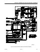
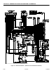
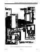
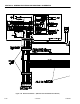
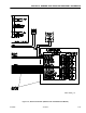
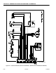

SECTION 9 - GENERAL ELECTRICAL INFORMATION & SCHEMATICS
9-36 – JLG Lift – 3121222
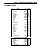
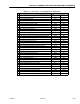
Table 9-11. Power Module - J2 (1001092456 Power Module ONLY)
Pin Function Type
1 Spare - (Connect to +BATT) Power Output
2 Positive Lif t Down Valve (High-Side Driver) Power Output
3 Spare Digital Input (High-Sensing) Digital Input
4 Spare Digital Input (High-Sensing) Digital Input
5 CANbus Low Serial I/O
6 CANbus High Serial I/O
7 Spare Positive Analog Reference (+5V ) Power Output
8 Platform EMS (Logic Supply for Platform Mode) Power Input
9 Negative Steer Left Solenoid Valve (Low-Side Driver) Digital Output
10 Switch Manual Brake Release (High-Sensing) Digital Input
11 Spare Digital Input (High-Sensing) Digital Input
12 Spare Digital Input (High-Sensing) Digital Input
13 Spare Digital Input (High-Sensing) Digital Input
14 Spare Negative Analog Reference (Connect to -B) Power Output
15 CANbus Shield (Connect to -B) Power Output
16 Negative Lift Down Valve (Low-Side Driver) Power Output
17 Negative Lift Up Solenoid Valve (Low-Side Driver) Digital Output
18 Negative Steer Right Solenoid Valve (Low-Side Driver) Digital Output
19 Spare Analog Input (0-5V) Analog Input
20 Spare Digital Output (Low-Side Driver) Digital Output
21 Spare Digital Output (Low-Side Driver) Digital Output
22 Negative for Overload Lamp (Low-Side Driver) Digital Output
23 Negative for Hourmeter (Low-Side Driver) Digital Output