
Service Manual Owner's manual
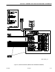
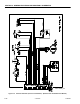

SECTION 9 - GENERAL ELECTRICAL INFORMATION & SCHEMATICS
3121222 – JLG Lift – 9-33
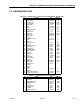
9.11 PIN INPUT/OUTPUT TYPES
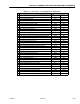
Table 9-3. Ground Board J1 - Connector X001 (1600346 Power Module ONLY)
Pin Function Type Range (V)
1Ground Power Output 0
2 Analyzer Power Power Output 12
3 RS-232 Receive Input/Output Comm
4 RS-232 Transmit Input/Output Comm
5 Platform EMS Input Vbatt
6Ground Power Output 0
7 Ignition Power Output Vbatt
8 Platform EMS Source Power Output Vbatt
9Not Used -- --
10 Left PHP Switch Input Vbatt
11 CAN Bus high Input/Output Comm
12 CAN Bus Low Input/Output Comm
13 CAN Bus Shield Power Output 0
14 Not Used -- --
15 Elevation Prox Switch Input 5
16 Ground Power Output 0
17 Not Used -- --
18 Right PHP Switch Input Vbatt
19 Ignition Power Output Vbatt
20 Brake Release Swtich Input Vbatt
21 Steer Left Coil Output Vbatt
22 Steer Right Coil Output Vbatt
23 Right Brake Release Output Vbatt
24 Left Brake Release Output Vbatt
25 Lift Up Coil Output Vbatt
26 Lift Down Coil Output PWM
27 Ground Power Output 0
28 Ground Alarm Output PWM
29 Charger Interlock Input Vbatt
30 Not Used -- --
31 CAN Bus High Input/Output Comm
32 CaN Bus Low Input/Output Comm
33 CAN Bus Shield Output 0
34 Not Used -- --
35 Not Used -- --
36 Not Used -- --
37 Ground Power Output 0
38 Not Used -- --
39 Master Ignition Connection Power Input Vbatt
40 Master Ground Connection Power Input 0
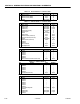
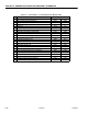
Table 9-4. Ground Board J2 - Connector X002
Pin Function Type Range (V)
1 Ignition Power Output Vbatt
2Ground EMS Power Input Vbatt
3 Platform EMS Source Power Input Vbatt
4 Ground Mode Select Input Vbatt
5Ground Power Output 0
6 Ground Lift Up Input Vbatt
7 Ground Lift Down Input Vbatt
8 Hour Meter Output Vbatt
9 Ground Overload Lamp Output Vbatt