
Service Manual Owner's manual

SECTION 8 - DIAGNOSTIC TROUBLE CODES
8-14 – JLG Lift – 3121222
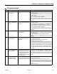
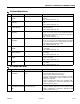
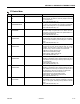
423 LIFT UP AT CUTBACK -
POWER MODULE CURRENT
LIMIT
The lift up portion of the power module
has reached thermal limit.
• Check for jammed or obstructed arm stack or pivot bushing.
• Check for excessively high current consumption in the pump,
ANALYZER -> DIAGNOSTICS -> PUMP -> PUMP CUR over 130
Amps with an empty deck.
• Refer to Pump Motor Electrical Evaluation in Section 4.8.
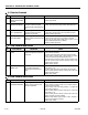
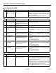
4-4 Battery Supply
DTC FAULT MESSAGE DESCRIPTION CHECK
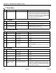
441 BATTERY VOLTAGE TOO
LOW - SYSTEM SHUTDOWN
The power module momentarily mea-
sured battery voltage under 14.5V
between ground board J1-39 and ground
board J1-40.
• Recharge batteries or check for damaged batteries.
• Check battery charger function.
442 BATTERY VOLTAGE TOO
HIGH - SYSTEM SHUTDOWN
The power module momentarily mea-
sured battery voltage > 37.0V.
• May be due to improper battery charging or incorrect voltage bat-
teries being used.
443 LSS BATTERY VOLTAGE
TOO HIGH
The load sensing system module
momentarily measured battery voltage >
34.0V.
• May be due to improper battery charging or incorrect voltage bat-
teries being used.
• Refer to Section 2.3: Troubleshooting in the LSS manual,
3124288.
444 LSS BATTERY VOLTAGE
TOO LOW
The load sensing system module
momentarily measured battery voltage <
9V.
• Recharge batteries or check for damaged batteries.
• Refer to Section 2.3: Troubleshooting in the LSS manual,
3124288.
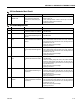
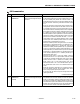
446 LOGIC SUPPLY VOLTAGE
OUT OF RANGE
The system module logic supply voltage
was measured to be out of normal operat-
ing range by the interface PCB (<11V).
• This may be caused by a loose battery terminal, severely dis-
charged batteries, damaged battery, or an improper wire harness
connection.
• Drive, Steer, and Lift Prevented
• ZAPI - HEALTH (Status LED) - ON
4421 LOGIC SUPPLY VOLTAGE
OUT OF RANGE
The system module logic supply voltage
was measured by the power PCB to be
more than 34V for 10uS.
• This may be caused by a loose battery terminal, severely dis-
charged batteries, damaged battery, or an improper wire harness
connection.
• Drive, Steer, and Lift Prevented
• ZAPI - HEALTH (Status LED) - ON
4422 LOGIC SUPPLY VOLTAGE
OUT OF RANGE
The system module logic supply voltage
was measured by the power PCB to be
less than 11V for 10uS.
• This may be caused by a loose battery terminal, severely dis-
charged batteries, damaged battery, or an improper wire harness
connection.
• Drive, Steer, and Lift Prevented
• ZAPI - HEALTH (Status LED) - ON
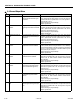
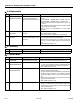
6-6 Communication
DTC FAULT MESSAGE DESCRIPTION CHECK
661 CANBUS FAILURE - POWER
MODULE
The control system failed to receive mes-
sages from the power module.
• Check for 24V between power module 12 position connector ter-
minal 1 and the power module B- terminal. If this is the problem,
the line contactor may be cycling on and off, making a clicking
noise when the machine is powered.
• Disconnect ground board J1 and power module connector.
Ground board socket J1-31 to power module connector socket
10 should have continuity. Ground board socket J1-32 to power
module connector socket 11 should have continuity.
• Turn on machine in platform mode. If DTC 662 is present, trouble-
shoot that DTC before continuing.
4-2 Thermal Limit (SOA)
DTC FAULT MESSAGE DESCRIPTION CHECK