
Service Manual Owner's manual

SECTION 8 - DIAGNOSTIC TROUBLE CODES
8-12 – JLG Lift – 3121222
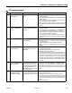
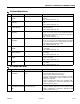
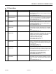
338 STEER LEFT OPEN CIRCUIT The ground board did not detect current
flow to the steer left solenoid during nor-
mal operation.
• Check for continuity through this circuit. Steer left solenoid resis-
tance should measure about 30 Ohms. The steer left solenoid is
powered with 24V from ground board J1-21, and its ground is to
ground board J1-30, 37.
• Inspect the wiring for physical damage.
•Replace ground board.
339 STEER RIGHT SHORT TO
BATTERY
The ground board detected voltage while
the steer right solenoid was commanded
off.
• Check for continuity through this circuit. Steer right solenoid
resistance should measure about 30 Ohms. The steer right sole-
noid is powered with 24V from ground board J1-22, and its
ground is to ground board J1-30, 37.
• Inspect the wiring for physical damage.
•Replace ground board.
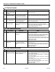
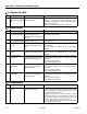
3310 STEER RIGHT OPEN CIR-
CUIT
The ground board did not detect current
flow to the steer right solenoid during nor-
mal operation.
• Check for continuity through this circuit. Steer right solenoid
resistance should measure about 30 Ohms. The steer right sole-
noid is powered with 24V from ground board J1-22, and its
ground is to ground board J1-30, 37.
• Inspect the wiring for physical damage.
•Replace ground board.
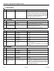
3311 GROUND ALARM SHORT TO
BATTERY
The ground board detected voltage while
the ground alarm was commanded off.
• Check for continuity through this circuit. The ground alarm sole-
noid is powered with 24V from ground board J1-19, its PWM sig-
nal is from ground board J1-28, and its ground is to ground board
J1-30, 37. There should be about 1500 Ohms between ground
alarm connector pin 1 and pin 3.
• Inspect the wiring for physical damage.
•Replace ground board.
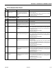
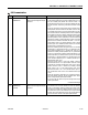
3312 LEFT BRAKE SHORT TO
BATTERY
The ground board detected voltage while
the left brake was commanded off.
• Check for continuity through this circuit. The left brake is powered
with 24V from ground board J1-23, and its ground is to ground
board J1-30, 37. Brake solenoid resistance should measure
about 20 Ohms.
• Inspect the wiring for physical damage.
•Replace ground board.
3313 RIGHT BRAKE SHORT TO
BATTERY
Voltage was detected on the right brake
solenoid when the ground board output
was commanded off during power-up.
• Check for continuity through this circuit. Brake solenoid resis-
tance should measure about 20 Ohms. The right brake is powered
with 24V from ground board J1-24, and its ground is to ground
board J1-30, 37.
• Inspect the wiring for physical damage.
•Replace ground board.
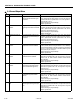
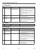
3314 LEFT BRAKE OPEN CIRCUIT Current flow to the left brake solenoid was
not detected during normal left brake
operation.
• Check for continuity through this circuit. The left brake is powered
with 24V from ground board J1-23, and its ground is to ground
board J1-30, 37. Brake solenoid resistance should measure
about 20 Ohms.
• Inspect the wiring for physical damage.
•Replace ground board.
3315 RIGHT BRAKE OPEN CIR-
CUIT
The ground board did not detect current
flow to the right brake during normal oper-
ation.
• Check for continuity through this circuit. Brake solenoid resis-
tance should measure about 20 Ohms. The right brake is powered
with 24V from ground board J1-24, and its ground is to ground
board J1-30, 37.
• Inspect the wiring for physical damage.
•Replace ground board.
3-3 Ground Output Driver
DTC FAULT MESSAGE DESCRIPTION CHECK