
Service Manual Owner's manual

SECTION 8 - DIAGNOSTIC TROUBLE CODES
8-8 – JLG Lift – 3121222
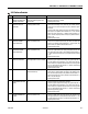
2210 TRIGGER CLOSED TOO
LONG WHILE IN NEUTRAL
The trigger switch was closed for more
than five seconds while the joystick was
centered.
• Check if the trigger switch is obstructed or jammed.
• Check the trigger switch signal and wiring to the platform board.
The trigger input (24V) is from platform board terminal J1-1, and
its output (24V when closed) is to platform board terminal J1-8.
• Replace platform board.
2232 FUNCTION PROBLEM -
DRIVE & LIFT BOTH OPEN
The drive and lift inputs are both de-
energized in Platform Mode.
• Check if either function is active, if Yes;
• Repair the wiring or switch to clear the message.
• ZAPI - HEALTH (Status LED) - ON
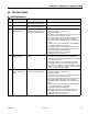
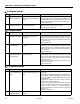
2-3 Ground Controls
DTC FAULT MESSAGE DESCRIPTION CHECK
231 FUNCTION PROBLEM - LIFT
PERMANENTLY SELECTED
The ground control box lift switch was
closed up or down, during power-up in
ground mode.
• Check if the lift switch is obstructed or jammed.
• Check the lift switch signal and wiring to the ground board. The lift
switch input (24V) is from ground board terminal J2-4, and its
outputs (24V when closed) are to ground board terminals J2-6,
J2-7 (up and down).
•Replace ground board.
232 GROUND LIFT UP / DOWN
ACTIVE TOGETHER
The lift up / down inputs are closed simul-
taneously.
• Check if the lift switch is obstructed or jammed.
• Check the lift switch signal and wiring to the ground board. The lift
switch input (24V) is from ground board terminal J2-4, and its
outputs (24V when closed) are to ground board terminals J2-6
(up), J2-7 (down).
•Replace ground board.
233 FUNCTION PROBLEM -
BRAKE RELEASE PERMA-
NENTLY SELECTED
The manual brake release switch was
closed during power-up.
• Check if the brake release switch is obstructed or jammed.
• Check the brake release switch signal and wiring to the ground
board. The brake release switch input (24V) is from ground board
terminal J1-19, and its output (24V when closed) is to ground
board terminal J1-20.
• If the brakes are released, the machine can be pushed or moved
without drive motor power.
•Replace ground board.
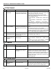
2-5 Function Prevented
DTC FAULT MESSAGE DESCRIPTION CHECK
251 ELEV ANGLE SENSOR
FAULTY - VOLTAGE OUT OF
RANGE
The elevation angle sensor input voltage
is outside the acceptable range of 0.10V -
4.50V.
• Check that the platform elevation sensor is securely mounted and
undamaged.
• Check voltage as displayed on ANALYZER -> DIAGNOSTICS ->
ELEV SENSOR -> ANGLE SNSR. Backprobe ground board J1-15.
If this voltage disagrees with the ANGLE SNSR voltage, replace
the ground board.
• Backprobe the elevation angle sensor connector. Terminal A
should be 4.7V, terminal C should be 0V.
• Check the elevation angle sensor signal and wiring to the ground
board. The elevation angle sensor input is from ground board ter-
minal J1-14 (4.7V), its output (0.1 - 1.2V when stowed) is to
ground board terminal J1-15, and its ground is to ground board
terminal J1-16.
• Replace the ground board.
252 ELEV ANGLE SENSOR HAS
NOT BEEN CALIBRATED
The elevation angle sensor has not been
calibrated.
• Calibrate the elevation angle sensor to clear fault. See Section 5.5.
2-2 Platform Controls
DTC FAULT MESSAGE DESCRIPTION CHECK