
Service Manual Owner's manual

SECTION 6 - MAST COMPONENTS
3121222 – JLG Lift – 6-15
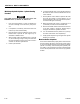
Hydraulic Cylinder - Disassembly
The following disassembly procedures shows the com-
plete disassembly sequence of the cylinder assembly.
However, your situation may not require complete disas-
sembly, choose which procedures are required to repair
the cylinder assembly for your situation.
DISASSEMBLY OF THE CYLINDER SHOULD BE PERFORMED ON
A CLEAN WORK SURFACE IN A DIRT FREE WORK AREA.
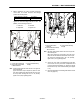
Removing the Valve Block Assembly
PROTECT THE CYLINDER ROD SURFACE. DAMAGE TO THE CYL-
INDER ROD CHROME FINISH DUE TO SCRATCHING, INDENDA-
TION, CHIPPING OR OTHERWISE WILL CAUSE EVENTUAL
GLAND SEAL FAILURE. THE CYLINDER ROD MUST BE
REPLACED IF DAMAGED.
1. Wrap the cylinder rod to protect it from damage,
then clamp the cylinder rod into a vise or device to
keep it from turning while removing the valve block
assembly.
2. Using the proper size wrench, (approx. 55mm -
2.165"), turn the valve block assembly counterclock-
wise to remove it from the end of the cylinder rod.
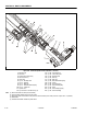
Cylinder #2 and #3 - Removal from Stack
1. Using the proper size wrench, (44mm - 1.732")
remove cylinder #2 rod attach cap by turning the
cap counterclockwise to remove.
2. Once the attach cap is removed from cylinder #2
rod, slide the cylinder #2 and #3 assembly out of
the joint sleeve. Move the cylinder #2 and #3
assembly to a suitable workbench for disassembly.
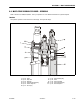
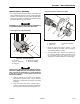
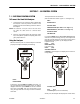
Figure 6-17. Valve Block - Removal
1. Valve Block
2. Cyl. #1 - Cylinder Rod
3. O-Ring Seal
4. Direction for Removing
5. Direction for Installing
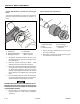
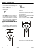
Figure 6-18. Cylinder #2 and #3 Assembly - Removal
1. Rod Attach Cap
2. Cylinder Joint
3. Cyl. #2 and #3 Assem-
bly