
Service Manual Owner's manual

SECTION 5 - CONTROL COMPONENTS
5-24 – JLG Lift – 3121222
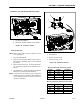
5.10 BATTERY CHARGER/INVERTER (OPTION)
- INSTALLATION
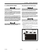
The battery charger-AC-inverter is located in the compart-
ment at the rear of the machine, remove the charger/step-
plate cover to gain access to the charger.
For further specification and troubleshooting information
refer to the manufacturers’ Charger/Inverter Owner’s
Guide shipped with the machine. Publication - RM1024-
JLG - Part # 3128406.
Also see Section 8 - Figure 9-20., Battery Charger/Inverter
Electrical Connection Schematic for more detailed con-
nection information.
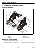
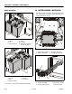
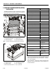
Battery Charger/Inverter Assembly - Installation
1. Charger/Inverter Assembly
2. Insulate Mounting Pad
3. Attach Screws (a)
4. Nylon Shoulder Washers
Note: (a) On final assembly apply Loctite #242 to screw threads
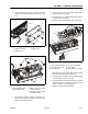
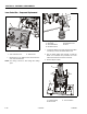
LED/Power/Interlock Cable - Identification
1. AC Output Connector
2. AC Input Connector
3. Remote On/Off Switch Cable
4. External DC Fuse Location
5. DC (–) Connection
6. DC (+) Connection
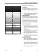
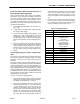
BATTERY CHARGER/AC INVERTER SPECIFICATION
AC INVERTER - SPECS
Output Power (Continuous) 1000 W
Output Power (Surge) 3000 W
AC Output Current 36 A
AC Output Voltage 115 to 125 VAC
Output Frequency 60 Hz
DC Input Voltage 21.2 to 29 VDC
Remote ON/OFF Yes
CHARGER - SPECS
Nominal DC Output Voltage 28 VDC
Maximum DC Output Voltage 33 VDC
Maximum DC Output Current 23 to 27 ADC
Required Interlock Current 1 A
Input Voltage (AC) 100 to 130 VAC
Nominal Input Voltage (AC) 120 VAC
Input Frequency 54 to 66 Hz
OPERATION
Charging Indicator Yellow LED
100% Charge Indicator Green LED
Fault Indicator Red LED
PROTECTION
Output Reverse DC Polarity 125 A Replaceable Fuse
Output AC Short Circuit Electronic Protection -
Automatic Reset
AC Overload 20 A Internal Slow Blow
Charger Fuse
DC Overload Voltage Limited - Internally
Controlled
MECHANICAL
Operating Temperature –40°F to +185°F
(–40°C to +85°C)
Housing Shock and Water Resistant
Aluminum