
Parts Manual User Manual


3120637 2-27
S
E
C
T
I
O
N
2
T
U
R
N
T
A
B
L
E
SECTION 2 TURNTABLE
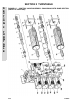
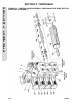
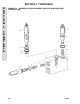
FIGURE 2-7. CONTROL VALVE ASSEMBLY - BANG-BANG WITH DUMP SECTION (PRIOR TO JUNE
1995)
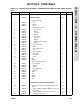
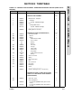
FIG & ITEM # PART NUMBER DESCRIPTION QTY. REV.
4640246 VALVE ASSEMBLY - 3 SECTION Ref. A
1 7002304 DUMP SECTION Ref.
Solenoid Assembly
2 7004823 Seat 1
7002378 O-Ring 1
3 7002229 Ball 1
Guide Tube Assembly 1
4 7004822 Cone, Female 1
7004840 O-Ring 1
5 7002346 Pin, Push 1
6 7004839 Plunger 1
7 7004838 Tube, Guide 1
8 7004841 Pin, Push 1
7002342 O-Ring 1
9 7002340 Guide, External Push Pin 1
7002337 O-Ring 1
10 7004834 Sleeve, Inner Flux 1
11 7002334 Spring 1
12 7004835 Sleeve, Outer Flux 1
13 7000417 Coil 1
14 7004836 Case, Solenoid 1
15 7002338 Plate, End 1
7002327 Nameplate 1
16 7004837 Screw 4
17 7002322 Seat 1
7004826 O-Ring 1
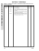
Main Relief (Poppet) Valve 1
18 7002321 Case, Poppet 1
19 7002328 Spring 1
20 7002294 Poppet 1
21 7002320 Seat, Adjustable 1
7004842 O-Ring 1
22 7002329 Spring 1
23 7002323 Plug 1
7000102 O-Ring 1
24 7002326 Orifice 1
25 7002324 Plug 1
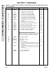
WORKING SECTIONS (STANDARD PARTS) Ref.
40 7004859 Solenoid Assembly (2 Per Section) (Includes Items
43-56)
A/R
41 7002274 Washer (7002315,7002316,7002317 Sections) (2
Per Section)
A/R
7003825 Washer (7003855 Sections) (2 Per Section) A/R
42 7002348 Spring (2 Per Section) A/R