
Parts Manual User Manual

3120637 7-3
S
E
C
T
I
O
N
7
E
L
E
C
T
R
I
C
A
L
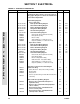
SECTION 7 ELECTRICAL
Boom Cables A/R
1060515 Cable, Electrical - 12/4 131ft/40m
1060516 Cable, Electrical - 16/30 131ft/40m
Boom Indicator Pendulum Wiring Diagrams: Ref.
4931959* 1st Generation (1st Eight Machines) Ref. A
4931960* 2nd Generation (Nineth Machines to Mid 1989) Ref. A
4931961* 3rd/4th/5th Generations (Mid 1989 to Present) Ref. B
3730024 Resistor - 100 Ohms 1
3730040
Resistor, Variable - 500 Ohms (2nd Generation
Only)
1
4931444/1281738
Dual Fuel Wiring Diagram (Prior to March 1995) Ref. F/G
4921305 Harness 1
4360201 Switch, Toggle (Located at Ground Control Box) 1
4932813* Dual Fuel Wiring Diagram (March 1995 to Present) Ref. —
4921763 Harness 1
4360201 Switch, Harness 1
4931671
Engine Distress Wiring Diagram - Deutz Engines
(Prior to September 1994)
Ref. B
4360179 Switch, Temperature 1
4360089 Flasher 1
3740013 Relay 1
4360065 Switch, Pressure 1
2920034 Lamp (Located at Platform Console) 1
3251695 Nameplate - Engine Distress 1
0255568
Engine Distress Wiring Diagram - Deutz Engines
(September 1994 to Present)
Ref. —
2920026 Lamp, Indicator 1
2920029 Bulb, Light 1
4360065 Switch, Oil Pressure 1
4360179 Switch, Temperature 1
3740049 Relay 1
0251683 Engine Run Light Wiring Diagram - Deutz Engines Ref. B
2920027 Lamp, Indicator 1
2920029 Bulb, Light 1
4360037 Switch, Pressure 1
1702528 Decal - Engine Run 1
0256598 Engine Run Light Wiring Diagram - Ford Engines Ref. 2
2920027 Lamp, Indicator 1
2920029 Bulb, Light 1
3990010 Diode 1
3252239 Decal - Engine Run 1
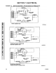
4932892 Engine Shut-Down Wiring Diagram - Deutz Engines Ref. —
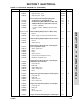
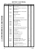
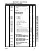
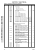
FIGURE 7-1. ELECTRICAL DIAGRAM LIST (CONTINUED)
FIG & ITEM # PART NUMBER DESCRIPTION QTY. REV.