
Parts Manual User Manual

3120637 1-5
S
E
C
T
I
O
N
1
F
R
A
M
E
SECTION 1 FRAME
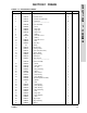
136 3532591 Plate, Cover 2
137 3300151 Nut, Acorn 4
138 4843028 Inner Axle Weldment (Rear Right Side) 1
139 4843023 Inner Axle Weldment (Rear Left Side) 1
140 0641505 Bolt 5/16"-18NC x 5/8" 16
141 4761500 Lockwasher 5/16" 16
142 4070670 Shim 1/8" A/R
143 4070672 Shim 1/32" A/R
144 4070674 Shim 1/16" A/R
0239152 WHEEL DRIVE INSTALLATION Ref. 3/B
201 2780155 Hub Assembly (See Figure 1-2 for Breakdown) 2
202 Brake Assembly Options: 2
0920072 Prior to March 1992 (See Figure 1-3 for Breakdown)
0920084 March 1992 to S/N 33476 (See Figure 1-4 for
Breakdown)
0920110 S/N 33476 to Present (See Figure 1-4 for
Breakdown)
0920119 Optional Replacement (Note: Can be used as
suitable replacement. Requires P/N 4300097
5-1/8” long Stud) (was p/n 0920117)
Note: Repair Kit p/n 7018612 & Mounting Face
Gasket p/n 7000731 are only Service Parts
available for Brake p/ns 0920119 & 0920117.
203 Motor Assembly Options: 2
Use 1001096405 Original Equipment (was p/n 3160132 - See Figure
1-5 for Breakdown)
1001096405 Service Replacement Kit (See Figure 1-6 for
Breakdown)
204 4300092 Stud 1/2"-13NC x 5 1/2" 4
205 4751800 Flatwasher 1/2" 4
206 4761800 Lockwasher 1/2" 4
207 3311801 Nut 1/2"-13NC 4
208 0642216 Bolt 3/4"-10NC x 2" 24
209 4762200 Lockwasher 3/4" Narrow 24
210 3300007 Lugnut 3/4"-16NF 24
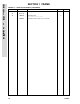
TIRE AND WHEEL INSTALLATIONS Ref.
Note: Assemblies may require ballast/foam filling to
manufacturer’s specifications prior to installing on
a machine. Refer to Operation & Safety or Service &
Maintenance Manuals. Purchase individual tire and/
or rim only if able to foam fill tire & wheel assembly,
otherwise, purchase complete assembly.
301 0239344
Tire and Wheel Assembly - 15 x 22.5 Foam-Filled (Prior
to April 1993)
A/R
0253929
Tire and Wheel Assembly - 385/65R22.5 Foam-Filled
(April 1993 to S/N 44997)
A/R
0259456
Tire and Wheel Assembly - 385/65R22.5 Foam-Filled
L.H. (S/N 44997 to Present)
2
0259442
Tire and Wheel Assembly - 385/65R22.5 Foam-Filled
R.H. (S/N 44997 to Present)
2
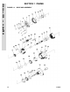
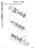
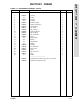
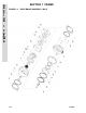
FIGURE 1-1. STEERING AND AXLE/WHEEL DRIVE INSTALLATIONS (CONTINUED)
FIG & ITEM # PART NUMBER DESCRIPTION QTY. REV.