Operators and Safety Manual Model 100HX 100HX+10 110HX 3120635 April 20, 2000 ANSI
– JLG Lift –
FOREWORD FOREWORD The purpose of this manual is to provide users with the operating procedures essential for the promotion of proper machine operation for its intended purpose. It is important to over-stress proper machine usage. All information in this manual should be READ and UNDERSTOOD before any attempt is made to operate the machine. YOUR OPERATING MANUAL IS YOUR MOST IMPORTANT TOOL - Keep it with the machine. REMEMBER ANY EQUIPMENT IS ONLY AS SAFE AS THE OPERATOR.
FOREWORD This page left blank intentionally.
FOREWORD All procedures herein are based on the use of the machine under proper operating conditions, with no deviations from original design intent... as per OSHA regulations and applicable ANSI standards. 5. All personnel in the platform shall, at all times, wear approved fall protection devices and other safety gear as required. 6. Load limits specified by the manufacturer shall not be exceeded. 7. Instruction and warning placards must be legible.
FOREWORD REVISON LOG September, 1988 August, 1989 August, 1997 January, 1999 Prop65 page added 4-1 d - Original Issue Revised Revised Revised Updated 4-20-00 Updated 4-20-00 – JLG Lift – 3120635
TABLE OF CONTENTS TABLE OF CONTENTS SUBJECT - SECTION, PARAGRAPH SECTION PAGE NO. - FOREWORD SECTION 1 - SAFETY PRECAUTIONS 1.1 1.2 1.3 1.4 1.5 1.6 1.7 General . . . . . . . . . . . . . . . . . . . . . . . . . . . . . . . . . . . . . . . . . . . . . . . . . . . . . . . . . . . . . . . . . . . . . .1-1 Driving/Towing. . . . . . . . . . . . . . . . . . . . . . . . . . . . . . . . . . . . . . . . . . . . . . . . . . . . . . . . . . . . . . . . .1-1 Electrocution Hazard. . . . . . . . . . . . . . . . . . .
TABLE OF CONTENTS (Continued) TABLE OF CONTENTS (continued) SUBJECT - SECTION, PARAGRAPH 5.12 5.13 5.14 5.15 5.16 5.17 PAGE NO. Motion Alarm . . . . . . . . . . . . . . . . . . . . . . . . . . . . . . . . . . . . . . . . . . . . . . . . . . . . . . . . . . . . . . . . . .5-2 Desert Environment Package . . . . . . . . . . . . . . . . . . . . . . . . . . . . . . . . . . . . . . . . . . . . . . . . . . . . .5-2 110 Volt/60Hz Generator. . . . . . . . . . . . . . . . . . . . . . . . . . . . . . . . . . . . .
SECTION 1 - SAFETY PRECAUTIONS SECTION 1. SAFETY PRECAUTIONS 1.1 GENERAL 1.2 DRIVING/TOWING This section prescribes the proper and safe practices for major areas of machine usage. In order to promote proper usage of the machine, it is mandatory that a daily routine be established based on instructions given in this section. A maintenance program must be also be established by a qualified person and must be followed to ensure that the machine is safe to operate.
SECTION 1 - SAFETY PRECAUTIONS Table 1-1. Minimum Safe Approach Distances (M.S.A.D.) to energized (exposed or insulated) power lines and parts Voltage Range (Phase to Phase) MINIMUM SAFE APPROACH DISTANCE in Feet (Meters) 0 to 300V AVOID CONTACT Over 300V to 50 KV 10 (3) Over 50KV to 200 KV 15 (5) Over 200 KV to 350 KV 20 (6) Over 350 KV to 500 KV 25 (8) Over 500 KV to 750 KV 35 (11) Over 750 KV to 1000 KV 45 (14) DANGER: DO NOT maneuver machine or personnel inside PROHIBITED ZONE.
SECTION 1 - SAFETY PRECAUTIONS • AN OPERATOR MUST NOT ACCEPT OPERATING RESPONSIBILITIES UNTIL ADEQUATE TRAINING HAS BEEN GIVEN BY COMPETENT AND AUTHORIZED PERSONS. • BEFORE OPERATION, CHECK WORK AREA FOR OVERHEAD ELECTRIC LINES, MACHINE TRAFFIC SUCH AS BRIDGE CRANES, HIGHWAY, RAILWAY AND CONSTRUCTION EQUIPMENT. • NEVER DISABLE OR MODIFY THE FOOTSWITCH OR ANY OTHER SAFETY DEVICE. ANY UNAUTHORIZED MODIFICATION OF THE MACHINE IS A SAFETY VIOLATION AND IS A VIOLATION OF OSHA REGULATIONS AND ANSI STANDARDS.
SECTION 1 - SAFETY PRECAUTIONS • ALWAYS POSITION BOOM OVER REAR (DRIVE) AXLE IN LINE WITH DIRECTION OF TRAVEL. REMEMBER, IF BOOM IS OVER FRONT (STEER) AXLE, DIRECTION OF STEER AND DRIVE MOVEMENT WILL BE OPPOSITE FROM NORMAL OPERATION. . • READ AND OBEY ALL DANGERS, WARNINGS, CAUT I O N S A N D O P E R AT I N G I N S T R U C T I O N S O N MACHINE AND IN THIS MANUAL. • BE FAMILIAR WITH LOCATION AND OPERATION OF GROUND STATION CONTROLS. • DO NOT USE DRIVE FUNCTION TO POSITION PLATFORM CLOSE TO OBSTACLES.
SECTION 1 - SAFETY PRECAUTIONS 1.6 OPERATION. • READ YOUR MANUAL. UNDERSTAND WHAT YOU’VE READ - THEN BEGIN OPERATIONS. • CHECK TRAVEL PATH FOR PERSONS, HOLES, BUMPS, DROP-OFFS, OBSTRUCTIONS, DEBRIS, AND COVERINGS WHICH MAY CONCEAL HOLES AND OTHER HAZARDS. • TRAVEL IS PERMITTED ON GRADES AND SIDESLOPES NO GREATER THAN THOSE INDICATED IN WARNING PLACARD AT MACHINE PLATFORM. • OPERATION WITH BOOM RAISED IS RESTRICTED TO FIRM, LEVEL AND UNIFORM SURFACE.
SECTION 1 - SAFETY PRECAUTIONS • TRANSFERS BETWEEN A STRUCTURE AND THE AERIAL PLATFORM EXPOSE OPERATORS TO FALL HAZARDS. THIS PRACTICE SHOULD BE DISCOURAGED WHEREVER POSSIBLE. WHERE TRANSFER MUST BE ACCOMPLISHED TO PERFORM THE JOB TWO LANYARDS WITH AN APPROVED FALL PROTECTION DEVICE WILL BE USED. ONE LANYARD SHOULD BE ATTACHED TO THE AERIAL PLATFORM. THE OTHER TO THE STRUCTURE.
SECTION 1 - SAFETY PRECAUTIONS FERING WITH OPERATING CONTROLS AND PERSONS IN PLATFORM. . • ENSURE THAT OPERATORS OF OTHER OVERHEAD AND FLOOR MACHINES ARE AWARE OF THE AERIAL PLATFORMS PRESENCE. DISCONNECT POWER TO OVERHEAD CRANES. POSITION BARRICADES ON FLOOR IF NECESSARY. • NEVER "SLAM" A CONTROL SWITCH OR LEVER THROUGH NEUTRAL TO THE OPPOSITE DIRECTION. ALWAYS RETURN SWITCH TO NEUTRAL AND STOP; THEN MOVE SWITCH TO THE DESIRED POSITION. OPERATE LEVERS WITH SLOW, EVEN PRESSURE.
SECTION 1 - SAFETY PRECAUTIONS • NEVER ATTEMPT TO FREE A MACHINE STUCK IN SOFT GROUND OR ASSIST A MACHINE UP A STEEP HILL OR RAMP BY USING BOOM "LIFT", "TELESCOPE", OR "SWING" FUNCTIONS. • NEVER ATTACH WIRE, CABLE, OR ANY SIMILAR ITEMS TO PLATFORM. • DO NOT PLACE BOOM OR PLATFORM AGAINST ANY STRUCTURE TO STEADY PLATFORM OR SUPPORT STRUCTURES. • DO NOT USE THE LIFT, SWING, OR TELESCOPE FUNCTIONS FOR THE BOOM, TO MOVE EITHER THE MACHINE OR OTHER OBJECTS.
SECTION 2 - PREPARATION AND INSPECTION SECTION 2. PREPARATION AND INSPECTION 2.1 GENERAL This section provides the necessary information needed by those personnel that are responsible to place the machine in operation readiness, and lists checks that are performed prior to use of the machine. It is important that the information contained in this section be read and understood before any attempt is made to operate the machine.
SECTION 2 - PREPARATION AND INSPECTION 8. Check extending axle assemblies for evidence of leakage and security; pressure lines for abnormal chafing drive hubs, hydraulic motors, brakes and hydraulic lines for damage and leaks. 9. Check extending axles for visible damage and loose or missing parts. 10. Check oscillating axle (if equipped) for loose, missing and worn parts, pivot pin and lockout cylinder pins for security, lockout cylinders and hydraulic hoses for damage and leaks.
SECTION 2 - PREPARATION AND INSPECTION Figure 2-1.
SECTION 2 - PREPARATION AND INSPECTION Platform 2. Placards. Keep all information and operating placards clean and unobstructed. Cover when spray painting or shot blasting to protect legibility. 1. Check platform and control console for damage, loose or missing parts, and security. 2. \Check control switches and levers for damage, loose or missing parts and security. Assure that all levers function properly. 3. Operator’s and Safety Manual. Ensure a copy of this manual and the ANSI A92.
SECTION 2 - PREPARATION AND INSPECTION Figure 2-2.
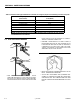
SECTION 2 - PREPARATION AND INSPECTION GENERAL Begin the “Walk-Around Inspection” at Item 1, as noted on the diagram. Continue to the right (counterclockwise viewed from top) checking each item in sequence for the conditions listed in the “Walk-Around Inspection Checklist”. TO AVOID INJURY, DO NOT OPERATE A MACHINE UNTIL ALL MALFUNCTIONS HAVE BEEN CORRECTED. USE OF A MALFUNCTIONING MACHINE IS A SAFETY VIOLATION. TO AVOID POSSIBLE INJURY, BE SURE MACHINE POWER IS “OFF” DURING WALK-AROUND INSPECTION.
SECTION 2 - PREPARATION AND INSPECTION 27. Muffler and Exhaust System - Properly secured, no evidence of leakage 32. Drive Hub, Left Rear - No visible damage, no evidence of leakage. 28. Cowling and Latches, Right Side - All cowling and latches in working condition, properly secured, no loose or missing part. 33. Wheel/Tire Assembly, Left Rear - Properly secured, no loose or missing lug nuts, no visible damage. 29.
SECTION 2 - PREPARATION AND INSPECTION 2.5 DAILY FUNCTIONAL CHECK THE LOAD MANAGEMENT SYSTEM AND THE AXLES (PROPER EXTENSION AND RETRACTION) MUST BE CHECKED PRIOR TO ANY OTHER SYSTEMS AND/OR FUNCTIONS. A functional check of all systems should be performed, once the walk-around inspection is complete, in an area free of overhead and ground level obstructions. First, using the ground controls, check all functions controlled by the ground controls.
SECTION 2 - PREPARATION AND INSPECTION Figure 2-5.
SECTION 2 - PREPARATION AND INSPECTION Table 2-1.
SECTION 2 - PREPARATION AND INSPECTION Table 2-1. Lubrication Chart Components Number/Type Lube Points Lube & Method Interval Hours N/A Chain Lube/Hot Oil Dip 1200 32 Boom Chains 33 Turntable Pivot Pin 2 Grease Fittings MPG - Pressure Gun 150 34 Extend-A-Reach Link Attach Pin 1 Grease Fitting MPG - Pressure Gun 150 35 Extend-A-Reach Pivot Pin 2 Grease Fittings MPG - Pressure Gun 150 Comments Includes extend and retract chains NOTES: Key to Lubricants: EO EPGL HO MPG t 2.
SECTION 2 - PREPARATION AND INSPECTION f. Extend the boom until it stops. The boom must stop on the white band on the mid boom section. IF BOOM CONTINUES TO TELESCOPE BEYOND SECOND MARKING BAND, RETRACT THE BOOM, IMMEDIATELY SHUT DOWN MACHINE AND CONTACT A QUALIFIED SERVICE PERSON. 14. Footswitch. FOOTSWITCH MUST BE ADJUSTED SO THAT FUNCTIONS WILL OPERATE WHEN PEDAL IS APPROXIMATELY AT ITS CENTER OF TRAVEL. IF SWITCH OPERATES WITHIN LAST 1/4" OF TRAVEL, TOP OR BOTTOM, IT SHOULD BE ADJUSTED. a.
SECTION 2 - PREPARATION AND INSPECTION 2.7 BATTERY MAINTENANCE TO AVOID INJURY FROM AN EXPLOSION, DO NOT SMOKE OR ALLOW SPARKS OR A FLAME NEAR BATTERY DURING SERVICING. ALWAYS WEAR EYE PROTECTION WHEN SERVICING BATTERIES. Battery Maintenance 1. The battery is maintenance free except for occasional battery terminal cleaning, as noted in the following. 2. Remove battery cables from each battery post one at a time, negative first. Clean cables with acid neutralizing solution (e.g.
Figure 2-6.
SECTION 3 - USER RESPONSIBILITIES AND MACHINE CONTROL SECTION 3. USER RESPONSIBILITIES AND MACHINE CONTROL 3.1 3. Knowledge and understanding of all safety work rules of the employer and of Federal, State and local statutes, including training in the recognition and avoidance of potential hazards in the work place; with particular attention to the work to be performed.
SECTION 3 - USER RESPONSIBILITIES AND MACHINE CONTROL 3.3 Stability OPERATING CHARACTERISTICS AND LIMITATIONS General A thorough knowledge of the operating characteristics and limitations of the machine is always the first requirement for any operator, regardless of the user’s experience with similar types of equipment. Placards This machine as originally manufactured by JLG Industries Inc.
SECTION 3 - USER RESPONSIBILITIES AND MACHINE CONTROL Figure 3-1.
SECTION 3 - USER RESPONSIBILITIES AND MACHINE CONTROL Figure 3-2.
SECTION 3 - USER RESPONSIBILITIES AND MACHINE CONTROL Figure 3-3.
SECTION 3 - USER RESPONSIBILITIES AND MACHINE CONTROL 3.4 3. Ignition Switch. CONTROLS AND INDICATORS The machine is equipped with an on-off ignition switch and a separate start push button switch on the ground control panel which supplies electrical power to the starter solenoid when the ignition switch is placed in the ON position and the START button is depressed.
SECTION 3 - USER RESPONSIBILITIES AND MACHINE CONTROL Figure 3-4.
SECTION 3 - USER RESPONSIBILITIES AND MACHINE CONTROL Figure 3-5.
SECTION 3 - USER RESPONSIBILITIES AND MACHINE CONTROL NOTE: Lift, Swing, and Telescope control switches are spring-loaded and will automatically return to neutral (off) when released. The push-button switch relays power to the glow plugs used to warm the air intake on cold start operations. 11. L.P. Gas/Gasoline Select Switch.
SECTION 3 - USER RESPONSIBILITIES AND MACHINE CONTROL 19. Start Button. to off while operating the machine will stop all functions and shut down the engine. The START button is a momentary contact, push button type switch that supplies electrical power to the starter solenoid, when the key switch and ignition switch are in the ON position and the start button is depressed. 3. Start Button. The START button is a momentary contact, pushbutton switch.
SECTION 3 - USER RESPONSIBILITIES AND MACHINE CONTROL Figure 3-6.
SECTION 3 - USER RESPONSIBILITIES AND MACHINE CONTROL Figure 3-7.
SECTION 3 - USER RESPONSIBILITIES AND MACHINE CONTROL NOTE: LIFT, SWING, and DRIVE control levers or switches are spring-loaded and will automatically return to the neutral (OFF) position when released. TO AVOID SERIOUS INJURY, DO NOT OPERATE THE MACHINE IF ANY CONTROL LEVERS OR TOGGLE SWITCHES CONTROLLING THE PLATFORM MOVEMENT DO NOT RETURN TO THE OFF OR NEUTRAL POSITION WHEN RELEASED. 6. Lift.
SECTION 3 - USER RESPONSIBILITIES AND MACHINE CONTROL 19. Auxiliary Power. The AUXILIARY POWER control switch energizes the electrically operated hydraulic pump, when actuated. The switch must be held on for duration of auxiliary pump use. The auxiliary pump functions to provide sufficient oil flow to operate the basic machine system should the main pump or engine fail. The auxiliary pump will operator boom lift, telescope and swing.
Figure 3-8.
Figure 3-9.
SECTION 3 - USER RESPONSIBILITIES AND MACHINE CONTROL 3120635 – JLG Lift – 3-17
SECTION 3 - USER RESPONSIBILITIES AND MACHINE CONTROL 3-18 – JLG Lift – 3120635
SECTION 3 - USER RESPONSIBILITIES AND MACHINE CONTROL Figure 3-10.
SECTION 3 - USER RESPONSIBILITIES AND MACHINE CONTROL Figure 3-11.
SECTION 3 - USER RESPONSIBILITIES AND MACHINE CONTROL Figure 3-12.
SECTION 3 - USER RESPONSIBILITIES AND MACHINE CONTROL Figure 3-13.
SECTION 4 - MACHINE OPERATION SECTION 4. MACHINE OPERATION 4.1 DESCRIPTION This machine is a self-propelled aerial work platform on the end of an elevating, telescoping and rotating boom. The JLG Lift’s intended purpose is to position personnel with their tools and supplies at positions above ground level. The machine can be used to reach work areas located above and over machinery or equipment. The JLG Lift has a primary operator Control Station in the platform.
SECTION 4 - MACHINE OPERATION 4.3 Shutdown Procedure ENGINE OPERATION NOTE: Initial starting should always be performed from the Ground Control station. IF AN ENGI NE MA LFUNCTI ON NECES SI TATES UNSCHEDULED SHUTDOWN, DETERMINE AND CORRECT CAUSE BEFORE RESUMING ANY OPERATION. 1. Remove all load and allow engine to operate at low speed setting for 3-5 minutes; this allows for further reduction of internal engine temperature. Starting Procedure. 1. Check engine oil.
SECTION 4 - MACHINE OPERATION Figure 4-1. Grade and Side Slope b. Position WHEEL MOTOR SPEED switch to LOW. c. Position PUMP VOLUME switch to LOW. BEFORE DRIVING, MAKE SURE BOOM IS POSITIONED OVER REAR AXLE. IF BOOM IS OVER FRONT AXLE (STEER WHEELS), STEER AND DRIVE CONTROLS WILL MOVE IN OPPOSITE DIRECTIONS TO MACHINE CONTROLS. 6. For traveling up grades, position switches as follows: a. Position HIGH ENGINE switch to HIGH. b. Position WHEEL MOTOR SPEED switch to LOW. Traveling Forward or Reverse c.
SECTION 4 - MACHINE OPERATION 4.6 Platform Rotation PARKING AND STOWING Park and stow machine as follows: 1. Depress footswitch to rotate platform to the left, PLATFORM ROTATE control is positioned to the LEFT and held until desired position is reached. 1. Park machine in travel position; boom lowered over rear, all access panels and doors closed and secured, ignition off, turntable locked. 2.
SECTION 4 - MACHINE OPERATION console to EXTEND until axles are fully extended and the AXLES SET light is on. Install axle lock pins. e. Position EXTENDABLE AXLE/STEER switch located on platform control console to RETRACT, until axles are fully retracted. 6. Position LIFT control to UP to lower the machine; elevate the boom sufficiently and reposition the boom over the steer wheel end of the machine. f. Align steer wheels and insert tie rod lock pins and steer cylinder pin. Install axle lock pins. g.
SECTION 4 - MACHINE OPERATION 4. Position the JACK/AXLES Select switch to AXLES. Then, position the JACK/AXLES control switch to left until the axles are fully extended. Install axle lock pins. If extending the steer axle, also install the tie rod lock pins and steer cylinder lock pin. NOTE: It may be necessary to elevate the wheels and jog the steer control for removal of lock pins. ENSURE THE JACK IS FULLY RETRACTED BEFORE OPERATING THE MACHINE. FAILURE TO DO SO COULD RESULT IN DAMAGE TO THE MACHINE.
Figure 4-3.
Figure 4-4.
SECTION 4 - MACHINE OPERATION 4.9 Raising and Lowering the Main Boom BOOM A RED TILT ALARM WARNING LIGHT, LOCATED ON THE CONTROL CONSOLE, LIGHTS WHEN THE CHASSIS IS ON A SEVERE SLOPE (5 DEGREES OR GREATER). DO NOT SWING, EXTEND OR RAISE BOOM ABOVE HORIZONTAL WHEN LIT. DO NOT DEPEND ON TILT ALARM AS A LEVEL INDICATOR FOR THE CHASSIS. TILT ALARM INDICATES CHASSIS IS ON A SEVERE SLOPE (5 DEGREES OR GREATER). CHASSIS MUST BE LEVEL BEFORE SWINGING, EXTENDING OR RAISING BOOM ABOVE HORIZONTAL.
SECTION 4 - MACHINE OPERATION 4.11 TIE DOWN AND LIFTING 4.13 TOWING (IF EQUIPPED) When transporting machine, boom must be in the stowed mode with turntable lock pin engaged and machine securely tied down to truck or trailer deck. Four tie down eyes are provided in the frame slab, one at each corner of the machine.
Figure 4-5.
SECTION 4 - MACHINE OPERATION After towing the machine, complete the following: 1. Actuate steer/tow selector valve for steering; push valve knob IN to the actuated position. 2. Reconnect drive hubs by inverting disconnect cap. (See Figure 4-5.) 3. Disconnect towbar from steering hitch and from towing vehicle. The machine is now in the driving mode. Figure 4-6.
SECTION 5 - OPTIONAL EQUIPMENT SECTION 5. OPTIONAL EQUIPMENT 5.1 2. If engine stumbles because of lack of gasoline, place the switch to LP position until engine regains smoothness, then return switch to GASOLINE position. Repeat as necessary until engine runs smoothly on gasoline. ROTATOR A Platform rotator allows for platform rotation 90 degrees from center in either direction. The rotator is designed to give added jobsite versatility.
SECTION 5 - OPTIONAL EQUIPMENT 5.8 ROTATING BEACON An amber or red rotating beacon may be installed on the hood or platform, and can be controlled by a two position toggle switch mounted on the platform control console. When the switch is placed in the ON position, the light is activated and provides a visual warning to the machine’s operation. 5.9 CYLINDER BELLOWS duty air cleaner, console cover, and air breather described in the Hostile Environment package in this section.
SECTION 6 - EMERGENCY PROCEDURES SECTION 6. EMERGENCY PROCEDURES 6.1 GENERAL This section provides information on the procedures to be followed and on the systems and controls to be used in the event an emergency situation is encountered during machine operation. Prior to operation of the machine and periodically thereafter, the entire operating manual, including this section, should be reviewed by all personnel whose responsibilities include any work or contact with the machine. 6.
SECTION 6 - EMERGENCY PROCEDURES functions. Training should include operation of the machine, review and understanding of this section and hands-on operation of the controls in simulated emergencies. until you are sure that all damage has been repaired, if required, and that all controls are operating correctly. 6.
SECTION 7 - INSPECTION AND REPAIR LOG SECTION 7. INSPECTION AND REPAIR LOG Table 7-1.
SECTION 7 - INSPECTION AND REPAIR LOG Table 7-1.
JLG Industries, Inc. TRANSFER OF OWNERSHIP To: JLG, Gradall, Lull and Sky Trak product owner: If you now own, but ARE NOT the original purchaser of the product covered by this manual, we would like to know who you are. For the purpose of receiving safety-related bulletins, it is very important to keep JLG Industries, Inc. updated with the current ownership of all JLG products. JLG maintains owner information for each JLG product and uses this information in cases where owner notification is necessary.
Corporate Office JLG Industries, Inc. 1 JLG Drive McConnellsburg PA. 17233-9533 USA Phone: (717) 485-5161 Fax: (717) 485-6417 JLG Worldwide Locations JLG Industries (Australia) P.O. Box 5119 11 Bolwarra Road Port Macquarie N.S.W.