
Service Manual

SECTION 6 - TROUBLESHOOTING
3121228 – JLG Lift – 6-9
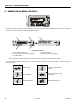
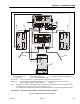
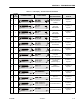
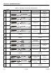
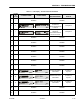
1. Ground Control Module (a) 4. Right Side Battery (b) 7. Power Cable To Right Drive Motor/Brake (a)
2. Left Side Battery (b) (c) 5. Traction Control Module (a) 8. Hydraulic Pump/Motor/Tank Assembly (b)
3. 175 Amp Fuse 6. Power Cable To Left Drive Motor/Brake (a)
Ground Control P1 - Horn, Alarm, Beacons, Lift Down Valve Harness (a) P4 - Platform Joystick Harness (a)
Module Plugs: P2 - Elevation/Speed, Charger Limit Switch Harness (a) P5 - Joystick Protocol Harness to Traction Control
P3 - Programmable Security Lock Harness (Option) (a) Module (a)
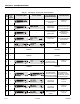
Notes: (a) Apply di-electric grease JLG Part Number 3020038 to wiring harness terminals, to prevent moisture from entering module.
(b) Seal NEG (–) and POS (+) posts with battery grease to prevent corrosion.
(c) An quick-disconnect is installed on the left battery (+) POSITIVE cable for easier power disconnect when servicing machine.
(See Figure 6-7.) - This section Troubleshooting for complete machine wiring schematic.
Figure 6-5. Component Electrical Connections.