
Parts Manual

7-6 10MSP 3121229
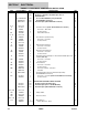
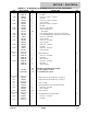
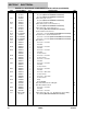
SECTION 7 ELECTRICAL
223 4923021 1 Cable, Battery (B+ to B–) (2 - 12Volt Batteries System Only) B
See Note 1 Boot, Red (Note: Not Available for Purchase)
See Note 1 Boot, Red (Note: Not Available for Purchase)
224 4923022 1 Cable, Battery (B+ to Fuse) B
See Note 2 Boot, Red (Note: Not Available for Purchase)
224A 4460216 2 Connector, Anderson (Blue)
225 4923023 1 Cable, Battery (Fuse to Ground Control +) A
See Note 2 Boot, Red (Note: Not Available for Purchase)
226 4923024 1 Cable, Battery (B– to Ground Control –) A
See Note 2 Boot, Black (Note: Not Available for Purchase)
227 4923028 1 Traction Module Power Harness C
227A Use 4923028 1 Connector - 2 Position (Note: Not Available for Purchase)
228 4923029 1 Ground Control to Traction Module Harness A
228A Use 4923029 1 Connector - 6 Position (Note: Not Available for Purchase)
228B Use 4923029 1 Connector - 6 Position (Note: Not Available for Purchase)
229 4923446 1 Main Harness D
229A 4460424 3 Connector - 2 Position
4460227 6 Pin, Male
229B 4460424 1 Connector - 2 Position
4460267 2 Pin, Male
229C 4460424 1 Connector - 2 Position
4460227 1 Pin, Male
4460226 1 Socket, Female
229D 4460320 3 Connector - 2 Position
4460226 6 Socket, Female
229E 4460320 2 Connector - 2 Position
4460227 4 Pin, Male
229F 4460320 1 Connector - 2 Position
4460227 1 Pin, Male
4460226 1 Socket, Female
229G 4460445 1 Connector - 3 Position
4460227 3 Pin, Male
229H 4460919 1 Connector - 20 Position
4460672 19 Socket, Female
229J 4460920 1 Connector - 14 Position
4460672 14 Socket, Female
229K 3740069 1 Relay
3990010 2 Diode 6A/600V
230 4933346 1 Drive Motor/Brake Electrical Diagram D
4923383 1 Drive Motor/Brake Harness E
230A 4460897 2 Connector - 2 Position
4460464 4 Pin, Male
230B 4461108 2 Connector - 4 Position
231 1001121700 3 Cable, Battery (B+ to B –) (4 - 6Volt Batteries System Only) A
See Note 2 Boot, Black (Note: Not Available for Purchase)
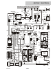
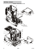
FIGURE 7-1. ELECTRICAL COMPONENTS INSTALLATION (CONTINUED)
ITEM PART NUMBER QTY DESCRIPTION REV