Broadcast Host™ ANALOG DESKTOP DIGITAL HYBRID User Guide JK Audio
Welcome Thank You Thank you for purchasing a JK Audio Broadcast Host Analog Desktop Digital Hybrid. Please read this guide for instructions on setting up and using your new product. Getting Assistance If you have technical or application questions: In the US & Canada, call us toll free at: 800-552-8346 All other countries dial: 815-786-2929 (M-F 8:30-5:00pm Central Time Zone) Email us at: support@jkaudio.com Or, check out our FAQ section for answers to common questions.
Contents Contents Overview Getting to know your Broadcast Host™ 2 Controls & Indicators 4 Inputs & Outputs 1 2 Getting Connected 6 Operation 8 Configuration 9 FAQs 10 Technical Information 12 Contents iii
Features Features 16 bit DSP Technology Caller XLR Line Output Auto-Answer (Switchable On/Off) 3.5mm Stereo Line Output Proprietary Auto Null Algorithm (50 dB null) 3.5 mm Stereo Headphone Jack Send XLR Line Input Mic/Line Switch 3.
Overview Introducing the Broadcast Host™ Broadcast Host will allow you to send and receive audio over analog telephone lines. While this may seem like a simple task that any telephone can do, the challenge is getting the best quality audio from such a limited audio path. What is a Digital Hybrid? The Broadcast Host digital hybrid connects audio signals to a standard analog telephone line without the variations in quality found with analog hybrids.
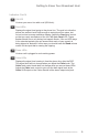
Getting to Know Your Broadcast Host 1 2 3 8 9 10 11 4 5 6 7 Controls & Indicators 1. Call Button Press this button to answer an incoming call or to connect your call through the hybrid if you have used an auxiliary phone to set up the call. 2. Drop Button Press this button to drop (hang up) a call. 3. Send 1 Level Adjusts the signal level that you are sending down the telephone line, through the female XLR input. 4.
Getting to Know Your Broadcast Host Indicators Cont’d 8. OH LED Lit when you are on line with a call (Off-Hook). 9. Send LEDs Displays the signal level going to the phone line. The goal is to drive the phone line audio at levels high enough to avoid phone line noise, but not so loud as to cause excessive clipping. Adjust the Send level control so that you rarely see flashes of the red -3dB peak Send LED. These flashes should occur only during loud speech bursts.
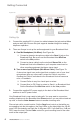
Getting to Know Your Broadcast Host 1 2 3 4 5 6 7 8 9 10 Inputs & Outputs 1. Line Jack Connect to a standard, single line, analog telephone line. 2. Phone Jack Connect a single line analog telephone for call setup, dialing, or call screening. (Optional). 3. Auto-Answer This switch enables Broadcast Host to automatically answer an incoming call and then disconnect after the caller hangs up. Auto answer will occur on the first ring. 4.
Getting to Know Your Broadcast Host Inputs & Outputs Cont’d 7. Send 2 Mono Input 3.5mm mono mini jack input for signals going into the phone line. Line level. 8. Stereo Output 3.5 mm stereo mini jack output contains both Send and Caller audio channels with levels determined by the Send 1 and Send 2 level controls and the Caller level control. Left channel contains your local Send audio and right channel contains the Caller’s audio from the telephone line. 9.
Getting Connected Figure 6a GUEST MODULE 1 Setting Up 1. Connect the supplied RJ-11 phone line cable between the jack marked Line and your wall jack. Be sure this jack supports standard single line analog telephone operation. 2. There are 2 ways to set up the audio equipment for your Broadcast Host: A. One Mic/Headphone (No Mixer): See Figure 6a. 1. Connect a dynamic microphone cable to the Send 1 jack on the Broadcast Host. Be sure to set the Broadcast Host Mic/Line switch to the Mic position. 2.
Getting Connected Figure 7a GUEST MODULE 1 MIC MIC MIC MIC UNBALANCED L L R R TAPE IN 1 2 TAPE OUT 3/4 5/6 7/8 MONO MONO MONO MONO BAL/ UNBAL LINE IN 1 BAL/ UNBAL LINE IN 2 LINE IN 3 BAL/ UNBAL LINE IN 5 BAL/ UNBAL LINE IN 7 BAL/ UNBAL BAL/ UNBAL BAL/ UNBAL MON SEND FOOTSWITCH BAL/ UNBAL INSERT INSERT LINE IN 4 LINE IN 6 LINE IN 8 MIC GAIN MIC GAIN MIC GAIN MIC GAIN U - - + GAIN GAIN LOW CUT U U - U U - U + GAIN U U EQ HI - + U - + U PHO
Operation Optional Jumper Settings If the incoming Caller level is too high and peaking the red -3 dB LED, you may need to change the setting of an internal jumper. Disconnect power from the hybrid and remove the cover of the Broadcast Host to locate Jumper 1. The default position for this jumper is closed (covering both pins). Changing the jumper to the open position (either remove the jumper or cover just one pin) will provide 6 dB attenuation of the incoming audio signal.
Configuration Remote Control Jack The RJ-45 jack on the back of the Broadcast Host provides connection to an optional JK Audio Guest Module 1 remote control, or it can be wired to the switch contacts on your broadcast console. Do not connect this jack to the network port on your computer. RJ-45 Pinout: 1: Ground 2: Call / Drop Control (main control pin) 3: Ring / OH LED 4: DTMF Input 5: +4.
FAQs 1. Will the digital hybrid provide phantom power for a condenser mic? No, this device will not provide phantom power. If you connect a microphone directly to the Broadcast Host, you should use a dynamic mic. 2. What happens if someone takes a second phone off-hook when the Broadcast Host is on a call? Broadcast Host will treat the other local voice the same as the caller.
FAQs 7. There is a loud hum on the output of my Broadcast Host, even when nothing else is connected. What else could it be? Make certain you are using the regulated power supply that was shipped with this unit. Power supplies are not all the same. 8. I need to be able to use my Broadcast Host at an office building but they only have a multi-line PBX phone system. Is there some way I can still connect this device? Talk to their phone specialist and ask for a standard analog line.
Technical Information Specifications Input Impedence / Level Female XLR (2) Mics 1k ohms / 15 mV RMS; -34 dBu nom.; Mic/Line Pad Switch = +6 dBu max 1/8” (3.5mm) Stereo Line 20k ohms / 250 mV RMS; -10 dBu nom. Output Balanced Male XLR 1/8” (3.5mm) Stereo Headphone 1/4” Stereo 12 200 ohms / 500 mV RMS; -4 dBu nom.; +14 dBu max; Caller Only 50 ohms / 250 mV RMS; +6 dBu max Left = Send; Right = Caller 8 ohms / 250 mW Mixed Send and Caller Phone Line Connector RJ11C Ringer 0.
Line level Send 2 Input Mic / Line Send Input Send 2 Level Send 1 Level Caller Digital Hybrid Monitor level Headphone Stereo Output R = Caller L= Send Caller Out Aux Phone Jack Phone Line Jack Technical Information Broadcast Host Block Diagram Block Diagram 13
FCC Registration FCC Registration Your new JK Audio product has been registered with the Federal Communications Commission (FCC). This product complies with the standards in Part 68 of the FCC rules. 1. Connection and use with the nationwide telephone network The FCC requires that you connect this telephone equipment to the national telephone network through a USOC RJ-11C modular telephone jack. This equipment may not be used with Party Line Service or Coin Telephone Lines.
FCC Part 15 Compliance FCC Part 15 Subpart A Compliance This equipment has been tested and found to comply with the limits for a Class A digital device, pursuant to Part 15 of the FCC Rules. These limits are designed to provide reasonable protection against harmful interference when the equipment is operated in a commercial environment.
™ Broadcast Host BROADCAST FIELD MIXER User Guide Version 9/24/13 JK Audio, Inc. 1311 E 6th St. Sandwich, IL 60548 United States Telephone: 815.786.2929 Toll Free: 1.800.jkaudio Fax: 815.786.8502 www.jkaudio.com © 2013 JK Audio, Inc. All rights reserved.