
Data Sheet


iolinker Family Data Sheet
3 Timing
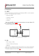
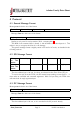
3.1 SPI Protocol
When writing out an SPI command that requires a reply from the FPGA, the master has to
keep writing out n + 1 zero bytes, where n is the number of bytes to be read back. This
means that with one byte delay, the FPGA will begin sending out its response bytes.
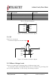
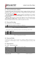
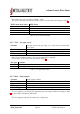
3.2 Interrupt Pin
The interrupt pin INT notifies about state change of any GPIO currently configured as input.
In idle mode it is open collector, which allows parallel connection of several chips on one
shared interrupt line. An external pullup can keep it high.
When an interrupt occurs, the FPGA pulls the INT signal low for 10ms. After each low
pulse a high pulse of at least 10ms length follows. Interrupts that occur during those 20ms
are ignored.
c
2017 jInvent. The specifications and information herein are subject to change without notice.
www.jinvent.de Page 6 iolinker introduction