
Data Sheet

iolinker Family Data Sheet
Contents
1 Introduction 2
1.1 Features . . . . . . . . . . . . . . . . . . . . . . . . . . . . . . . . . . . . 2
1.2 Introduction . . . . . . . . . . . . . . . . . . . . . . . . . . . . . . . . . . 2
1.3 Applications . . . . . . . . . . . . . . . . . . . . . . . . . . . . . . . . . . 2
2 Interfaces 4
2.1 UART . . . . . . . . . . . . . . . . . . . . . . . . . . . . . . . . . . . . . 4
2.2 SPI . . . . . . . . . . . . . . . . . . . . . . . . . . . . . . . . . . . . . . . 4
2.3 I2C . . . . . . . . . . . . . . . . . . . . . . . . . . . . . . . . . . . . . . . 5
2.4 Different Voltage Levels . . . . . . . . . . . . . . . . . . . . . . . . . . . . 5
3 Timing 6
3.1 SPI Protocol . . . . . . . . . . . . . . . . . . . . . . . . . . . . . . . . . . 6
3.2 Interrupt Pin . . . . . . . . . . . . . . . . . . . . . . . . . . . . . . . . . . 6
4 Protocol 7
4.1 General Message Format . . . . . . . . . . . . . . . . . . . . . . . . . . . . 7
4.2 SPI Message Format . . . . . . . . . . . . . . . . . . . . . . . . . . . . . . 7
4.3 I2C Message Format . . . . . . . . . . . . . . . . . . . . . . . . . . . . . . 7
4.4 Command Destination Address . . . . . . . . . . . . . . . . . . . . . . . . 8
4.5 Command Encoding . . . . . . . . . . . . . . . . . . . . . . . . . . . . . . 8
4.6 Command Buffer . . . . . . . . . . . . . . . . . . . . . . . . . . . . . . . . 8
4.7 Command List . . . . . . . . . . . . . . . . . . . . . . . . . . . . . . . . . 8
4.7.1 VER – Retrieve chip version . . . . . . . . . . . . . . . . . . . . . . 8
4.7.2 TYP – Pin type set-up . . . . . . . . . . . . . . . . . . . . . . . . . 9
4.7.3 REA – Read register . . . . . . . . . . . . . . . . . . . . . . . . . . 9
4.7.4 REA – Read pin states . . . . . . . . . . . . . . . . . . . . . . . . . 10
4.7.5 SET – Set output states . . . . . . . . . . . . . . . . . . . . . . . . 10
4.7.6 SYN – Synchronize Buffered IO State . . . . . . . . . . . . . . . . . 11
4.7.7 TRG – Trigger IO State Buffer Execution . . . . . . . . . . . . . . . 11
4.7.8 LNK – Set-up IO matrix . . . . . . . . . . . . . . . . . . . . . . . . 11
4.7.9 PWM – Configure Pulse Width Modulation . . . . . . . . . . . . . . 11
4.7.10 CLR – Clear special pin functions . . . . . . . . . . . . . . . . . . . 12
4.7.11 RST – Reset volatile memory . . . . . . . . . . . . . . . . . . . . . 12
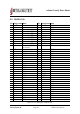
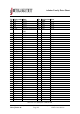
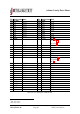
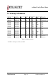
5 Pin Addresses 13
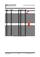
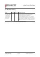
6 Default Pin States 14
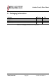
7 Application Notes 15
7.1 Basic schematic for TQFP-100 . . . . . . . . . . . . . . . . . . . . . . . . 15
7.2 Basic schematic for WLCSP-81 . . . . . . . . . . . . . . . . . . . . . . . . 16
7.3 High Power LED Example . . . . . . . . . . . . . . . . . . . . . . . . . . . 16
c
2017 jInvent. The specifications and information herein are subject to change without notice.
www.jinvent.de Page 36 iolinker introduction